
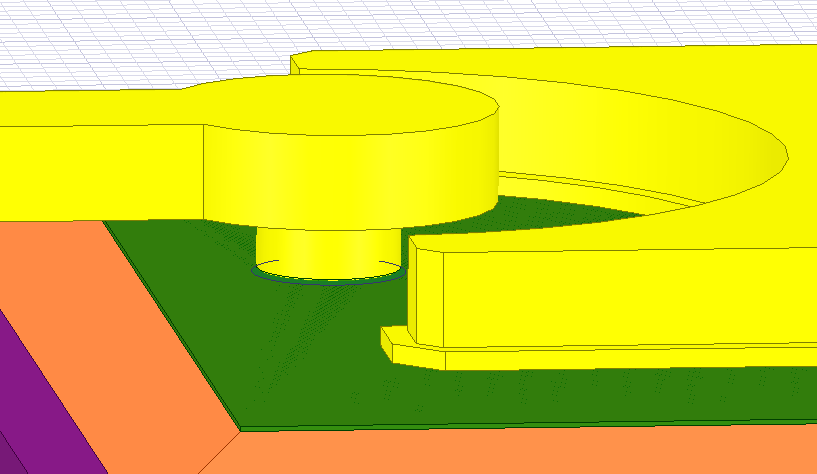
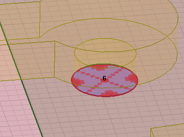
How to set a coaxial waveport for a Schottky diode 3-D model?


Viewing 1 reply thread
- The topic ‘How to set a coaxial waveport for a Schottky diode 3-D model?’ is closed to new replies.


