
TAGGED: node-selection, selection
-
-
September 22, 2021 at 9:27 am
MickMack
SubscriberHi folks,
I have checked some other discussions but i have not been able to find a solution, hence the new post.
Simply i want to be able to select a line of nodes or even a single node within a solid, as shown in the image below i want to select a line of nodes at the centre of the bolt.
September 22, 2021 at 9:50 amErik Kostson
Ansys EmployeeHi
First of all, only if you have a split edge at the centre will the mesher guaranteed put nodes on that centre line - if there is no edge, then it can not be sure that the nodes will be on that centre line.
Having done the above, then one can select the edge, create a Named Selection - then highlight that named selection right mouse button click on it and choose create nodal named selection (that is shown below, created from Selection).
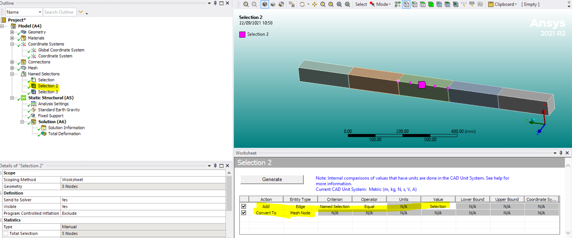
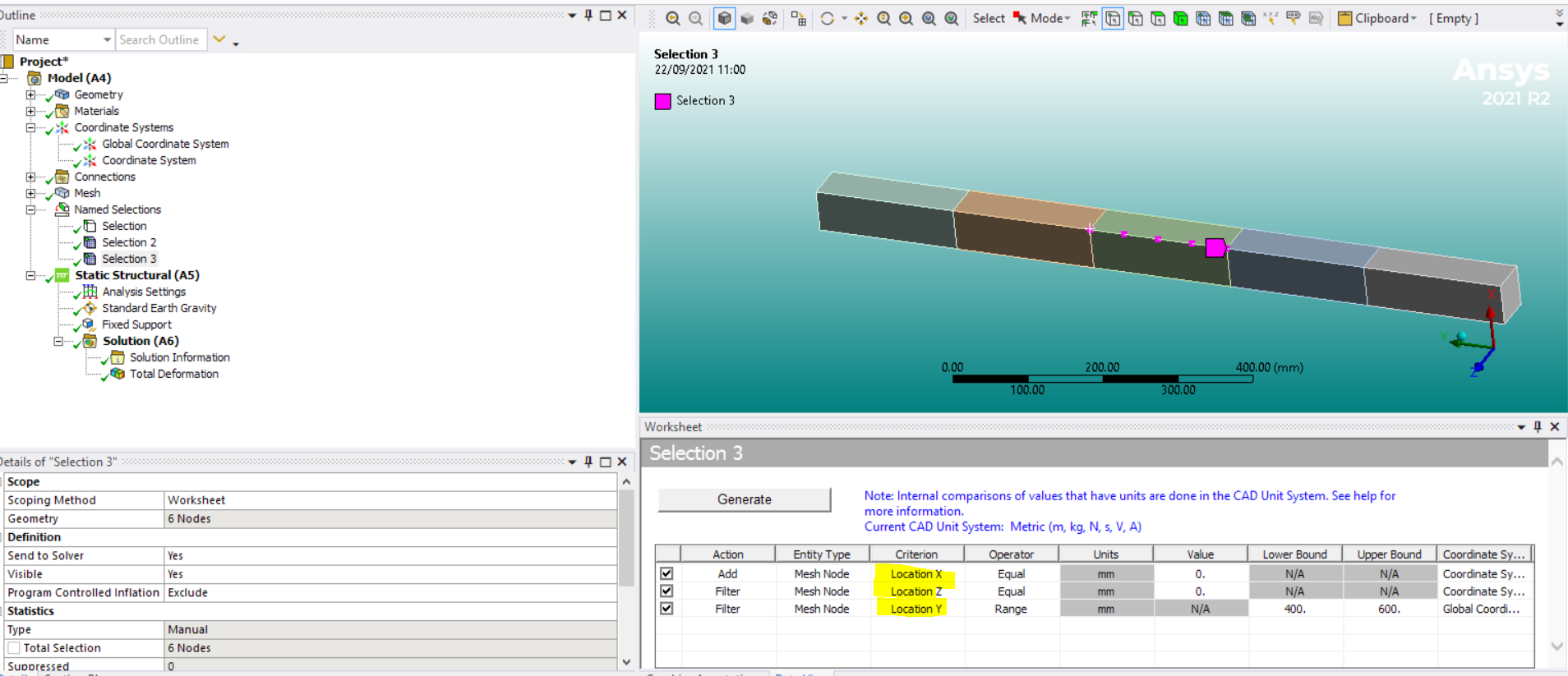
Another way is to use the worksheet in named selections to choose nodes at a certain location (you could define a local coordi. system there on the edge and use X=0, Y=0,.. to select them in the worksheet).
Hope this helps
Erik
September 22, 2021 at 9:56 amVigneswaran Sridharan
Ansys EmployeeHi One can select a particular node/nodes from WB GUI and right-click to select the option 'Create Named Selection'.
If the nodes are to be selected from surface/bodies, then create a Named Selection for the particular SUrface/body. Right-click the Named Selection and select 'Create Nodal Named Selection'.
You could try to model the bolts as line body with 'fixed joint' or 'MPC Bonded contact'.
Vigneswaran
September 22, 2021 at 11:10 amSubscriberThanks you both very much for your answers.
I had avoided inserting a cut face as it was causing problems with my multizone hex mesh generation, and i did not want to apply the changes to a single bolt to resolve them. In any case if i have to do this after i have tried the other options i will have no choice.
Again the prompt response is much appreciated.
Cheers Michael
September 22, 2021 at 3:04 pmpeteroznewman
SubscriberIn Mechanical, you can create a Path that runs along the centerline of the bolt. ANSYS will interpolate the stress from the elements that intersect that Path and give you a chart of stress vs Path length.
The Path is created under the Construction Geometry folder.
October 2, 2021 at 1:48 pmSubscriberHi
Thank you for your suggestion i will keep this in mind.
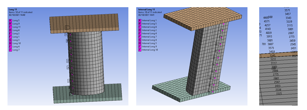
By way of an update i am carrying out a different simulation, compression test on a concrete cylinder. I wanted to plot stress vrs strain at regularly spaced nodes along a vertical line on the external surface (long1-11) and at another parralel line within the cylinder (Internal Long 1-11).
To do this i turned on the node numbers and orientated themodel soi could read the node id's. It is not elegant but in this instance it worked.
The alternative options are detailed above particularly creating a local co-ord system and also splitting the solid.
Thanks to everyone for there assistance with this.
Cheers Michael
October 13, 2021 at 12:47 pmSubscriberHi
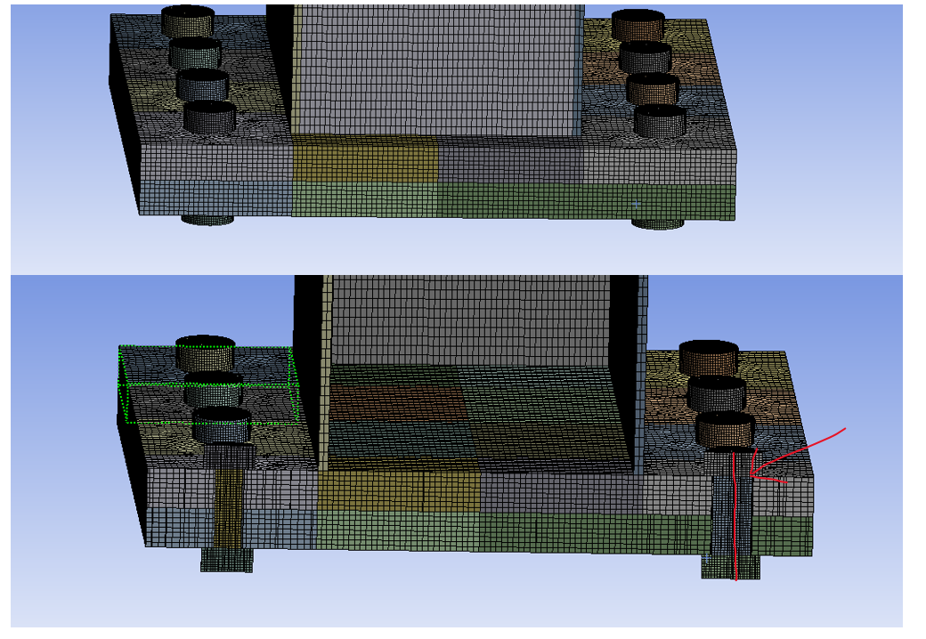
Using the split body and split face features in Spaceclaim is the most effective way to do this. After splitting the body of the cylinder and the faces i added all the solids to a single component, opened the compnent and then used the share command.
This does alter the results from the original single solid body, but in this instance the difference is acceptable.
Please see wireframe of solid below.

Viewing 6 reply threads- The topic ‘How to select an internal node within a body?’ is closed to new replies.
Innovation Space Trending discussions
- The legend values are not changing.
- LPBF Simulation of dissimilar materials in ANSYS mechanical (Thermal Transient)
- Convergence error in modal analysis
- APDL, memory, solid
- How to model a bimodular material in Mechanical
- Meaning of the error
- Simulate a fan on the end of shaft
- Real Life Example of a non-symmetric eigenvalue problem
- Nonlinear load cases combinations
- How can the results of Pressures and Motions for all elements be obtained?
Top Contributors
-
peteroznewman
 4167
4167 -
scabo
 1487
1487 -
Dennis Chen
 1338
1338 -
javat33489
 1171
1171 -
Shyam Prasad V Atri
1021
Top Rated Tags
© 2025 Copyright ANSYS, Inc. All rights reserved.
Ansys does not support the usage of unauthorized Ansys software. Please visit www.ansys.com to obtain an official distribution.
-


The Ansys Learning Forum is a public forum. You are prohibited from providing (i) information that is confidential to You, your employer, or any third party, (ii) Personal Data or individually identifiable health information, (iii) any information that is U.S. Government Classified, Controlled Unclassified Information, International Traffic in Arms Regulators (ITAR) or Export Administration Regulators (EAR) controlled or otherwise have been determined by the United States Government or by a foreign government to require protection against unauthorized disclosure for reasons of national security, or (iv) topics or information restricted by the People's Republic of China data protection and privacy laws.


