-
-
March 2, 2022 at 6:49 am
taosif_alam
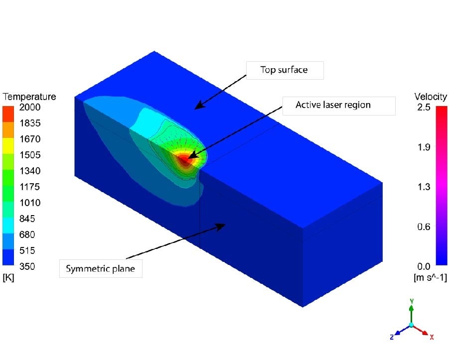
SubscriberI am simulating the temperature and velocity distribution of a laser powder bed fusion process with a moving laser heat source. I have attached the temperature distribution and velocity vector figures (full view and zoomed view). Only half domain is simulated due to symmetric nature of the moving laser. The top surface is a powder region and laser heat source moves over it. At the top surface, it has only convection and radiation heat loss boundary condition. The top surface also have Marangoni stress boundary condition the surface tension gradient is negative. This means that the velocity flow direction will be opposite to the direction of the temperature gradient. The picture of temperature gradient vector directions is also attached which shows they are directed inward towards the high temperature region.
March 2, 2022 at 1:49 pmKarthik Remella
AdministratorHello:
If I understand your modeling approach right, you are solving the NS equations in the solid region as well. This will ask the solver to compute the velocity in the solid region too. In reality, the velocity of the solid region should be zero but your modeling approach will estimate some small finite velocity in this region. Is my understanding correct?
Karthik
March 2, 2022 at 3:08 pmSubscriberHi Karthik Yes, you are correct. Do you have any suggestion how to resolve this ? I have tried with increasing mushy zone constant values. But, makes the continuity residuals values very high and solution diverges eventually. Also, the direction of those small unwanted velocities are opposite to the general flow direction. Do you have any idea why the result is showing this? Your thought regarding this will be highly appreciated.
Thanks.
March 3, 2022 at 2:21 pmAdministratorHello:
I'm not sure if there is a fool-proof solution for this. As I said, since you are solving the NS equations on the Solid side as well, you will have some unwanted velocity. If it is the properties of the solid (density and viscosity) that would help mimic the solid-like behavior. Just a curious thought - have you increased the viscosity of the solid to a very large number? This may cause additional stability issues.
Karthik
March 3, 2022 at 4:59 pmSubscriberHi, Karthik Thanks for your reply again. FYI, I have increased the viscosity of the solid phase 10^5 times higher than the liquid phase using UDF. The viscosity of the fluid is in the order of 10^-5 (in SI units)and viscosity of the solid taken as 1. And you are right, I was having stability issues for all other types of meshes except polyhedral meshes. If, I try to increase mushy zone constant more than 10^7 or 10^8, the continuity was diverging. What do you suggest regarding viscosity data should I use for solid and liquid phase ?
Viewing 4 reply threads- The topic ‘How to resolve unwanted velocity flow created at the edge of the melting temperature line’ is closed to new replies.
Innovation Space Trending discussions
 Top Contributors
-
peteroznewman
 6835
6835 -
scabo
 1906
1906 -
Dennis Chen
 1522
1522 -
javat33489
 1343
1343 -
NickFL
1152
Top Rated Tags
© 2026 Copyright ANSYS, Inc. All rights reserved.
Ansys does not support the usage of unauthorized Ansys software. Please visit www.ansys.com to obtain an official distribution.
-
Ansys Assistant will be unavailable on the Learning Forum starting January 30. An upgraded version is coming soon. We apologize for any inconvenience and appreciate your patience. Stay tuned for updates.