TAGGED: constraint-issue, error, solver
-
-
February 15, 2022 at 3:15 pm
phanicmsf
SubscriberNot enough constraints appear to be applied to prevent rigid body motion. This may lead to solution warnings or errors. Check results carefully.
Hi, I'm doing a simulation in ANSYS where the part is technically free to expand in all directions and I was wondering how to minimally constrain the system to avoid rigid body motion without imposing some additional stress.
February 15, 2022 at 7:03 pmJJ_Thompson
SubscriberFree to expand in all direction? what kind of model are you solving?
Just guessing without knowing any details, did you try to add weak springs?
February 16, 2022 at 4:37 ampeteroznewman
SubscriberOne method is to use a kinematic mount to ground as described here: /forum/index.php?p=/discussion/33280/how-to-avoid-rigid-motion-for-thermal-stress-simulaitons
Another method is to use a single Remote Displacement, Behavior = Deformable on one face of your model and set all six DOF to zero.
February 16, 2022 at 10:32 amphanicmsf
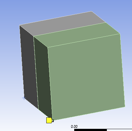
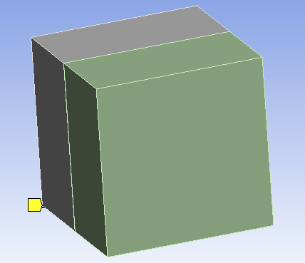
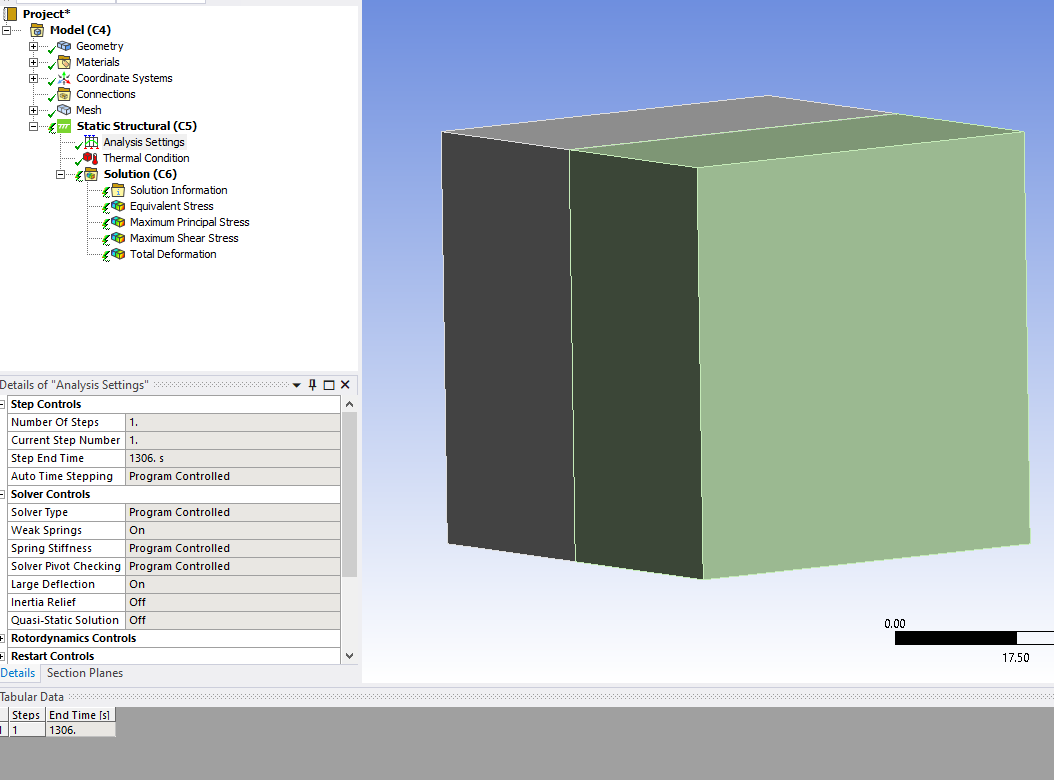
SubscriberThis is my Model.
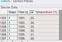
Homogenous cooling of a cube made of different materials.
If I added weak springs then I am able to get solution solved without getting errors.
Does this boundary conditons (weak springs ON) accepteble inorder to look stresses developed due to differen CTE (alpha) values of two materials during homogenous cooling?

February 16, 2022 at 12:41 pmpeteroznewman
SubscriberWeak springs will add a very small force to the model as it changes size. The hope is that the force is small enough to ignore.
A kinematic mount adds zero force, so there is no effect on the stress due to purely thermal loads.
February 16, 2022 at 1:57 pmphanicmsf
SubscriberThank you . I will implement as explained by you.
February 16, 2022 at 3:12 pmFebruary 16, 2022 at 3:37 pmpeteroznewman
SubscriberWhat is that Pressure Load you now show? You can't have a pressure and use a support on only three nodes of a solid mesh. The Kinematic mount is for purely thermal loads.
This is how to make a Kinematic mount for purely thermal loads. Use three vertices on one face. If you choose a face that is parallel to the XY plane, the constraint pattern is shown below. Use three displacement BCs. The first one sets X, Y, and Z = 0. The second one, spaced in X from the first point sets Y and Z = 0. The third one, spaced in Y from the first two, sets Z = 0.
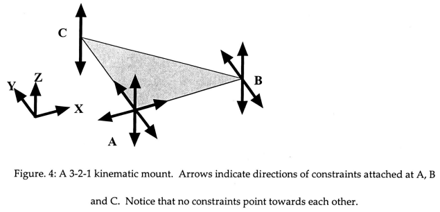 Instead of those three displacement constraints that make a Kinematic mount, you can use one Remote Displacement on the whole face, and set all six DOF to 0.
Choose one or the other, don't do both.
If you need a pressure load, then use the Remote Displacement method. What faces do the pressure loads act on?
February 17, 2022 at 11:17 amphanicmsf
SubscriberI want to see effect of mechanical tensile load acting on the block after cooling from 1326 to 20 degrees.
A tensile load of 200 Mpa acts on the two faces.(In the Fig shown as compressive).
So can I use Kinematic mount BC as explained above ?
Or Should I use any other BCs?
Any suggestions about applying BC using Remote Displacement method in this case will be a great help to me.
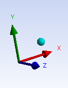
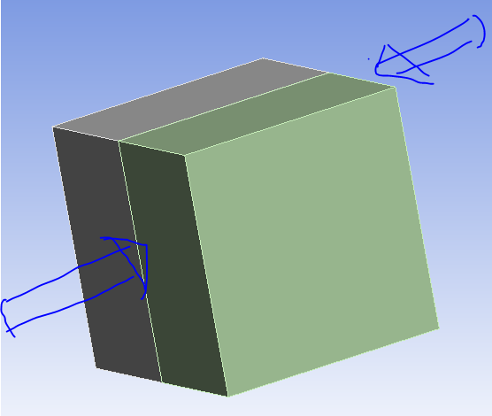
February 17, 2022 at 11:38 amphanicmsf
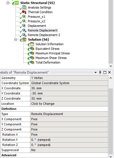
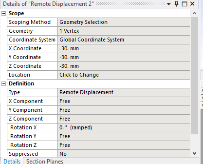
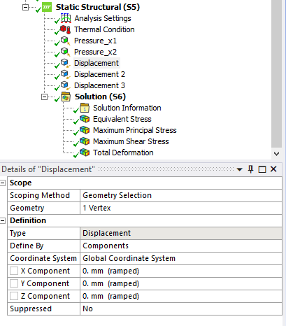
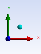
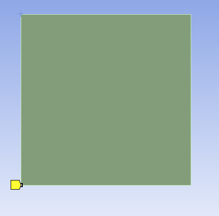
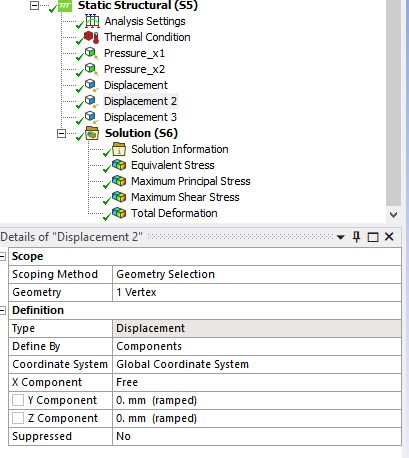
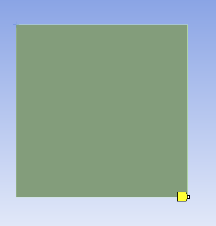
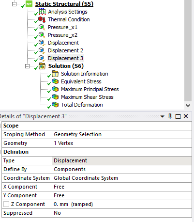
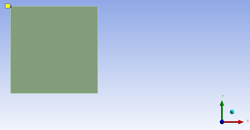
Subscriber. Does the following way of applying Kinematic mount for Thermal cooling makes sense as explained by your answer.
One Face parallel to XY plane is selected. Displacement is given on vertex at origin , Displacement2 is given on vertex on X axies, Displacement3 is given on vetex on Y axies of the selected face.
February 17, 2022 at 12:26 pmpeteroznewman
SubscriberYes, you have correctly applied the kinematic mount for the thermal load, but since you want to apply a pressure to the faces, you can't use three single nodes. Since your geometry and the loads have two planes of symmetry, you can use that in the constraints.
Use a plane parallel to YZ that goes through the center of the blocks Split the blocks using that plane and delete one half, keeping the blocks on the +X side. The cut faces get a Displacement BC of X=0 and Y, Z Free. That allows you to apply the pressure load on just one side and have a BC to push against.
It will be convenient to make a plane parallel to the XZ plane that goes through the center of the half blocks and split the blocks again. Delete half again, keeping the 1/4 blocks on the +Y side. Apply a Displacement BC on the newly cut faces of Y = 0 leaving X and Z Free.
There is one DOF left to constrain, which is motion along the Z axis. This could be achieved by selecting the faces on the +Z side of the quarter blocks and using a Remote Displacement, set Z = 0 leaving the other five DOF Free.
February 17, 2022 at 1:12 pmphanicmsf
SubscriberThank you for your expalanation.
I cannot model with 1/4th part. After running for this simple part later I need to change the geometry without symmetry.
Example I thought of building is shown in the fig. (half part of model is shown)
I would like to see stresses at the interface by introducing different gemetry types inside the cube.(sphere, ellipsoid with different orientations etc)
Inside objects has different material properties and outside object has different properties. In such a cases I cannot cut the whole cube into 1/4th and apply BC.
Instead I would like to build full model and Observe stress distribution after cooling with different interior gemetries.
So I would like to give Generalized BC which will solve my problem for all cases.
Load steps are 1) THERMAL COOLING from 1326 to 20
2) Mechanical tensile loads on faces parallel to YZplane
This pic is simulation result from literature.

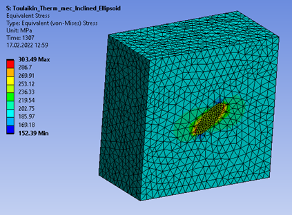 So in my case inside a cube I need to introduce ellipse with different orientaions and apply pressure load on one face then observe stress distribution.
I just want to apply pressure on any two parallel faces. (Pressure load is not applied on all faces). (Means entire body is subjected to tensile loading).
February 17, 2022 at 2:23 pmpeteroznewman
SubscriberIn the final models, there is a shape of one different material in the center of a cube. Is that cube material surrounding the shape all the same material?
February 17, 2022 at 2:47 pmphanicmsf
Subscriber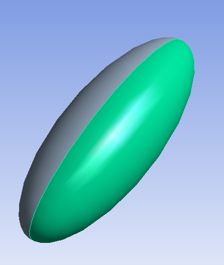
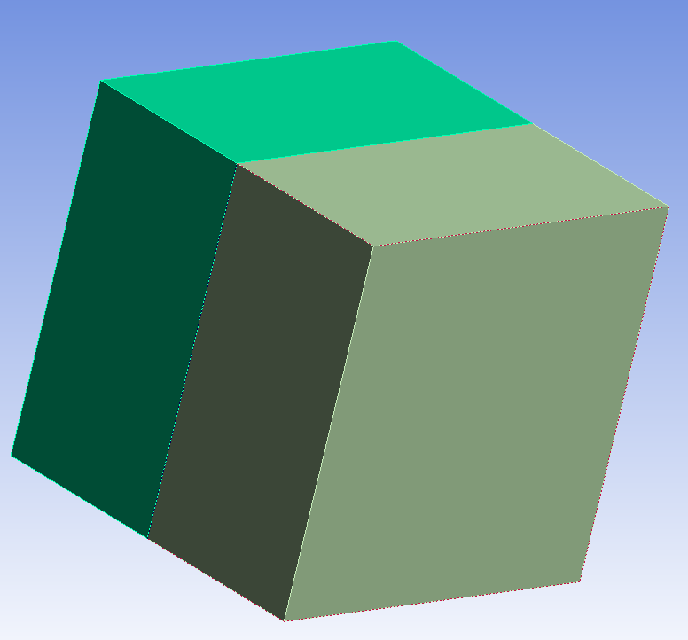
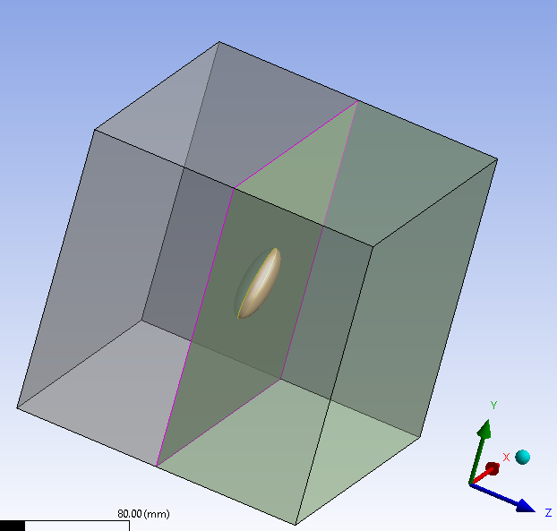
The ellipsoid having dimensions of Rminor=3mm and Rmajor = 8 mm is Inclined at an angle of 45 degress with Gloabal cartesian X axies is kept inside the cube having a dimensios of 60*60*60mm.
In other words cuboid volume is sliced with the inclined ellipsoid volume.
Entire cube is made of one material and entire ellipsoid is made of another material.
I think these images will give an idea.
February 17, 2022 at 5:03 pmpeteroznewman
SubscriberThe cube at the beginning will have flat faces from the geometry at 1326 C. When it is cooled to 20 C with an object at the center with a different CTE, the face of the cube will no longer be flat. The surface error of the highs and lows of each face can be measured at the end of the thermal part of the simulation.
How will a tensile force be applied to the faces? Are those faces going to be bonded to a flat face of a tensile testing fixture? How thick is the adhesive that will bond the cube to the test part? Compare the thickness of the adhesive with the maximum Peak-to-Valley of the surface error. What fraction of the adhesive thickness is the P-V dimension?
February 18, 2022 at 10:07 amphanicmsf
Subscriber1) For simulation case Tensile force is considered as perfectbond throughout the step. No adhesives are considered for bonding.
I just want look at distribution of stresses in an ideal case.
Lets say a tied bond.
2) Considering the size of Ellipsoid inside the cube to be smaller and assuming the outer faces of the cube remain flat after uniform cooling and then Tensile load is applied at two opposite faces. In such a case what type of BCs must be applied for the problem to get solved.
3)For an easy understanding assuming the outer faces of the cube remain flat after uniform cooling lets say a compressive load applied on two opposite faces (Not a tensile load with adhesive bond or other connection type) then what type of BCs must be considered in Ansys mechanical ?
February 18, 2022 at 10:40 pmpeteroznewman
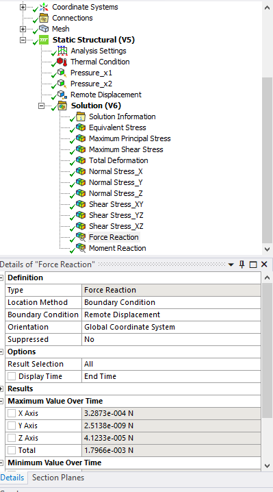
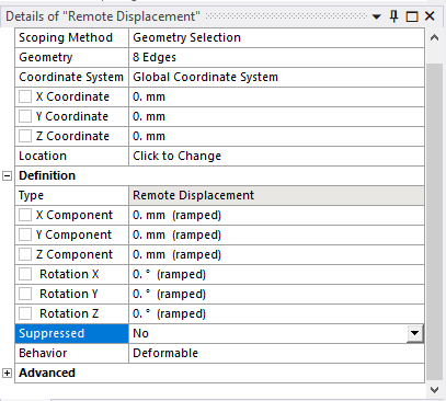
SubscriberSelect the eight edges parallel to Z on the perimeter of the cube and create a Remote Displacement, Behavior = Deformable. Set all six DOF to 0. A node will be created in the center of the cube, but it won't interfere with the sample. This one constraint will hold the average of the nodes on all eight edges to be fixed at 0. That will allow a strain free contraction of the cube around the inclusion.
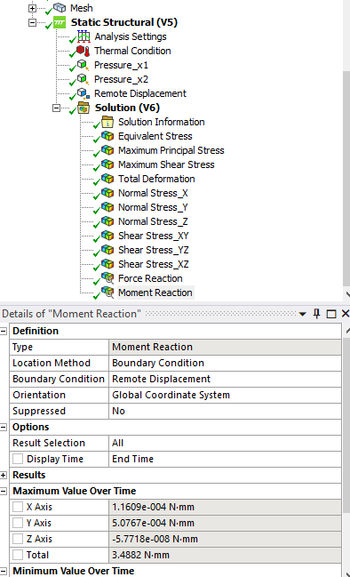
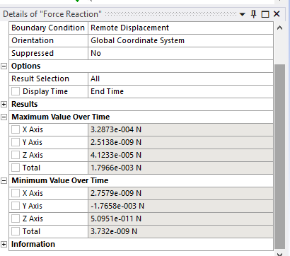
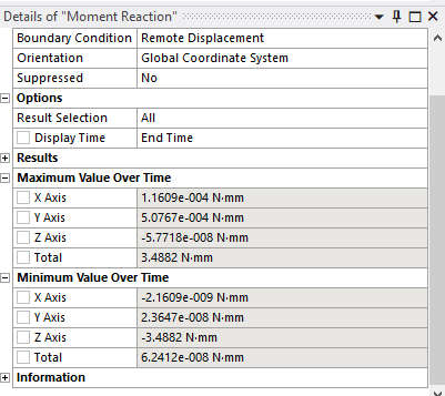
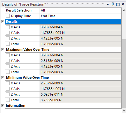
Since the two faces on either side are the same area and parallel, you can apply equal and opposite tensile or compressive forces, which should cancel each other out at the Remote Displacement point. In the Solution, Insert a Probe on the Reaction Forces and Reaction Moments on this Remote Displacement. The values should be very small.
February 21, 2022 at 1:21 pmFebruary 21, 2022 at 1:23 pmFebruary 21, 2022 at 5:39 pmpeteroznewman
SubscriberI'm interested in the Results, which you have collapsed, not the Minimum Value Over Time.
February 22, 2022 at 11:19 amFebruary 22, 2022 at 12:41 pmpeteroznewman
SubscriberPressure acts normal to the surface, and the surfaces which started out as flat are no longer flat, so the pressure is applying a moment to the cube.
If you don't want that moment, apply a force to the faces of the cube (or make it a directional pressure). That way, the moments will become much smaller.
February 23, 2022 at 9:44 amphanicmsf
SubscriberThanks a lot for your kind insights.
I will make changes and check the results.
Viewing 22 reply threads- The topic ‘How to prevent rigid motion in ANSYS Static Structural?’ is closed to new replies.
Innovation SpaceTrending discussionsTop Contributors-
5064
-
1770
-
1387
-
1248
-
1021
Top Rated Tags© 2026 Copyright ANSYS, Inc. All rights reserved.
Ansys does not support the usage of unauthorized Ansys software. Please visit www.ansys.com to obtain an official distribution.
-

