-
-
April 22, 2022 at 6:50 am
lkl
SubscriberHi,
I would like to ask if I have a beam and want it to deflect to a certain millimetre before touching the spring with certain stiffness. How do I model this kind of situation in ANSYS?
Thank you.
April 22, 2022 at 7:50 ampeteroznewman
SubscriberAnother way to do that is to use a COMBIN40 spring element which supports a GAP capability.
/forum/discussion/1110/how-do-i-implement-combin40-for-springs-in-wb
April 22, 2022 at 9:13 amlkl
Subscriber
Sorry I am a newbie, how do I create a line body that represent the spring. Since it has a gap between the spring and the body, could it still be as a contact between them?
April 22, 2022 at 9:16 amlkl
Subscriber
I looked at the forum, there are two stiffness k1 and k2 but only have one stiffness constant of the spring, does it mean K1 is 0 and K2 is my stiffness constant of the spring after the gap?
April 22, 2022 at 9:39 amErKo
Ansys Employee
Be aware that in the suggested post (link below for reference), the real constants are likely not defined in the correct order (see help manual for combin40 on the real constants and their order, and the direction that the element operate in - this is keyoption 3).
Also you only need the GAP and K2 real constants since you do not care about the fslide I suppose.
So as an example:
r,_sid,,,,gapp,,k2
/forum/discussion/1110/how-do-i-implement-combin40-for-springs-in-wb
April 23, 2022 at 8:02 amlkl
SubscriberHi @ekostson,
Thank you both for giving me the link. I do not a fslide, I would like to model such that when I applied the load, the beam will first deflect till it is let's say 16mm gap before touching the spring with a stiffness 21000N/mm.
A few questions to ask about this combin40 function:
1) when I insert the spring, do I still need to input the longitudinal stiffness or should I choose tabular. If I choose tabular, how would the input of displacement and force work since I have the stiffness of the spring 21000N/mm?
2) I assumed I have to input something in pt 1) before going to input the commands (APDL), is that how it should work?
3) The beam will deflect in the y direction but I do not a K1 for the sliding. Since, I do not have any fslide and K1. Should I put K1 =0 , fslide =0 or omit K1 and fslide in my command?

4) That is how my command is written, is that how it should be done?
et,_sid,combin40
Keyopt,_sid,3,2
K1=0
K2=21000
C=0
GAP=16
FSLIDE=0
r,_sid,K1,K2,C,GAP,FSLIDE
5) Eventually, if all works, how would I be able to check it is working what I want it to be?
Appreciate your advice. Thank you.
April 24, 2022 at 11:35 pmpeteroznewman
Subscriber5) Create a model where you apply a displacement of the beam tip in the y direction of 20 mm. Under Analysis Settings, turn on Auto Time Stepping, set the Initial and Minimum Substeps to 100, and the Maximum Substeps to 1000. Also turn on Large Deflection. This will cause the solution to plot a result every 0.2 mm. In the Solution, insert a Probe on the Reaction Force of the Displacement. You will see a first slope from zero up to 16 mm then a change in slope as the spring engages.
April 25, 2022 at 6:55 amErKo
Ansys Employee
Please read through the posts we write - your command snippet as I said is wrong (my previous post).
Use the one I have added there (previous post).
As for 1)&2), just add a 1 N/mm, since it does not matter what value we put, as this stiffness is not important since it will not be used and be overwritten by the command snippet. Also make sure you use Nmm as units.
All the best
Erik
April 26, 2022 at 5:57 pmlkl
Subscriber&
Thank you for the guidance.
For simplification, I created a rail section (5m) to try out the function of combin40 gap function with a load of 12000N applied at the end and included the spring below it. The other end is a fixed end at the rail foot

I used the command below based on the order and also created the auto time stepping.
et,_sid,combin40
Keyopt,_sid,3,2
GAP=16
K2=21000
r,_sid, GAP, K2
I received a lot of errors and warning messages, the model cannot be solved.

Could advice what are the errors that I have made so that I can solve the model?
Thank you.
April 27, 2022 at 1:41 ampeteroznewman
SubscriberPlease follow the advice previously given. Don't use a Force, create a model where you apply a Displacement of the beam tip in the y direction of 20 mm. Under Analysis Settings, turn on Auto Time Stepping, set the Initial and Minimum Substeps to 100, and the Maximum Substeps to 1000. Also turn on Large Deflection. This will cause the solution to plot a result every 0.2 mm. In the Solution, insert a Probe on the Reaction Force of the Displacement. You will see a first slope from zero up to 16 mm then a change in slope as the spring engages.
April 27, 2022 at 7:42 amlkl
Subscriber.
I have created a displacement at the other end with a constant of 20mm in the y-direction. Setting substeps and turn on large deflection. However, the graph plot is as shown below for the force reaction did not show to have two slopes. Or is there a way to plot it?
 Solving the model is ok but I still get some warning messages. How do I solve the warning message?
 Can I assume that the y-direction constant of 20mm is just to try out the gap combin40 works? As my model will require to know how much it deflect at the rail foot.
Thank you.
April 27, 2022 at 7:49 amErKo
Ansys Employee
As we said you have not implemented correctly the command snippet.
See my post where I have stated it is :
---
et,_sid,combin40
Keyopt,_sid,3,2
GAPP=16
K2=21000
r,_sid,,,,GAPP,,K2
----
in your case .
So you need the commas in the r command as shown above (r,_sid,,,,GAPP,,K2), and not just : r,_sid, GAP, K2,
as they (commas) define the order of the real constants which are determined by the element (combin40 - see help for real constants and their order).
Hope it is clear now.
Also yes, the 20 mm displacement is to see that it works.
Erik
April 27, 2022 at 9:13 amlkl
SubscriberHI @ekostson Thank you for pointing out my mistake. I have edited the commands, and the graph of the reaction force shown this. How do I convert it showing the displacement graph?
et,_sid,combin40
Keyopt,_sid,3,2
GAP=16
K2=21000
r,_sid,,,,GAP,,K2
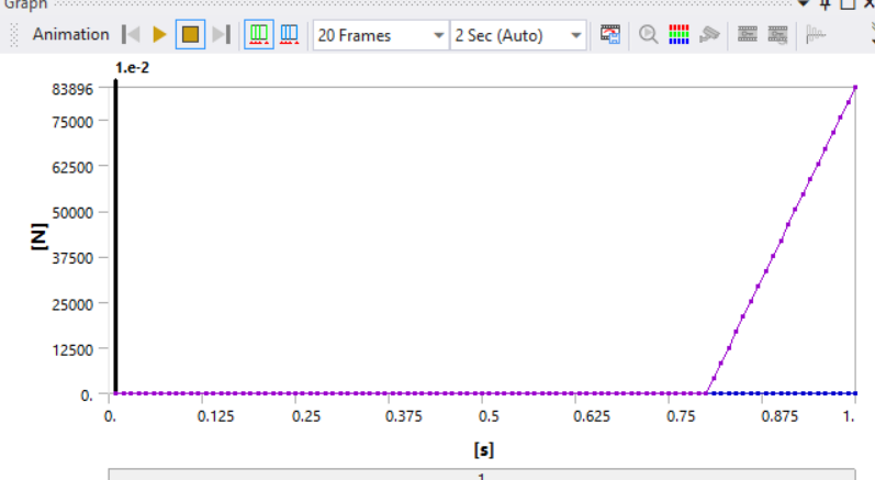 I still get the warning messages, same as above. How do I solve it?
 Thank you.
April 27, 2022 at 9:31 amErKo
Ansys Employee
Use
r,_sid,,,,GAPP,,K2
GAPP=16
or something else than GAP because GAP is a reserved APDL command so you do not want to use that.
So that seems to work since you have 4 mm when the spring is active so 4mm*21000 N/mm = 84 000 N which is what the above reaction plot shows.
I assume you want to plot the displacement versus reaction, then look on charts in workbench.
Also search the internet and the forum on this topic.
All the best
Erik
April 27, 2022 at 9:56 amApril 27, 2022 at 12:09 pmlkl
SubscriberHi @ekostson &.
Thanks for the advice. Very much appreciated. Can I plot the graph which I can see that after 16mm the springs start to engage?
As this is a just a simplification of model to see if the gap analysis works, I have a few queries on it:
1) do I need a certain constant value for the y axis displacement or let's say I only need the gap as 16, I will put the constant value as 16? (However, by putting a constant value, the rail will only deflect to the max of 16mm, am I right?)
2) do I have to place a y direction displacement at all the springs will be ? (I am asking because, I am trying to model several rail seats by springs with certain rail seat spacing such that the rail is not fully supported on the rail seat and this gap may happen in the middle of the span length)
3) I do try to make y direction displacement as free, but the model cannot be solved with the error as show below.

April 27, 2022 at 12:14 pmApril 27, 2022 at 8:31 pmpeteroznewman
Subscriber1) There is a gap to a spring and the gap is 16 mm so at 16 mm of deflection, whether caused by a force or a displacement, the gap closes and the spring begins to be compressed. The tip does not stop moving, it just takes more force to move it further.
2) You don't have to use displacement in your model, you can use force. You used displacement in a model to test and verify that the spring was working correctly because the displacement is an input that will cause a known tip displacement. When applying a force, if you don't know the stiffness in the rail you don't know what the tip deflection will be. The reaction force graph shows the gap part of the spring definition is working correctly.
3) What do you mean you make the y direction free? Show exactly the loads and supports you are using. Do you mean you deleted the displacement and are now using a force? If the force is too large, like 1 million times too large, that can cause an error. What is the magnitude of the force you applied? How does that compare with 84,000 N?
April 28, 2022 at 7:34 amlkl
Subscriber
Thank you for your advice.
For 2): Noted, now I know that I could just use force to create deflection, I thought I also need the displacement function.
For 3): Yes I have suppressed the displacement that I have created previously, the rest is kept as what it is. The model no longer able to solve. I used the same force of 120000N.
 For the function you have mentioned previously on this --> Under Analysis Settings, turn on Auto Time Stepping, set the Initial and Minimum Substeps to 100, and the Maximum Substeps to 1000. Also turn on Large Deflection. Is this necessary or can be kept as default for the time step and need to on large deflection?
I have created another model which is what I wanted to find. I have two fixed ends at the bottom of rail foot ends with a load acting on the mid span. The circle area, the three springs is input with the command of the combin 40 gap analysis.
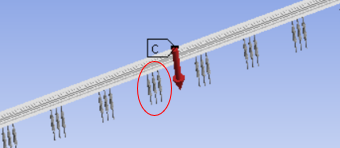 I am able to solve the model but I am not sure if it is working properly. I try to find the force reaction of the deflection at one of the springs but it is all zero. Could advice how do I check if the model is working properly. The result of this did show that the deflection is more than if it is in a normal supported condition. Could this reflect that the model is working well? (the result analysis is based on the the step control is all set as default and no large deflection.)
Appreciate your advice.
April 29, 2022 at 8:08 amlkl
SubscriberHi Any advice?
Thank you.
May 1, 2022 at 3:49 amlkl
Subscriber
Really appreciate if you could give me some advice on this.
Thank you.
May 2, 2022 at 12:04 ampeteroznewman
SubscriberIn Workbench, use File - Archive to create a .wbpz file that you can attach to your reply and state the version of ANSYS you are using. Then I can open your file and see all details.
May 2, 2022 at 8:22 amlkl
Subscriber
I have remodel a simplify model, everything works well except on one warning message as shown below. Is this a concern?
 I did not put the function as mentioned in previous post "Under Analysis Settings, turn on Auto Time Stepping, set the Initial and Minimum Substeps to 100, and the Maximum Substeps to 1000. Also turn on Large Deflection", it is all under default setting. Is this ok?
Could you advice how should I do to ensure the model is working properly? Only three of the springs I created had the combin40 function.
Appreciate your advice . Thank you.
May 2, 2022 at 3:45 pmMay 2, 2022 at 4:01 pmlkl
Subscriber
My model to be exact is actually a rail profile rather than an I-beam. Is this also applicable? Is there any issue with my model?
Thank you.
May 2, 2022 at 6:24 pmpeteroznewman
SubscriberI used your solid model to create a beam with the exact profile you had in the rail. That conversion from solid to beam element is highly automated in SpaceClaim.
The problem using loads on a single vertex/node is that since the area is zero, the stress is theoretically infinite and as a practical matter, the node tends to sink below the surface of the mesh.
May 3, 2022 at 8:27 amMay 5, 2022 at 9:44 amlkl
Subscriber
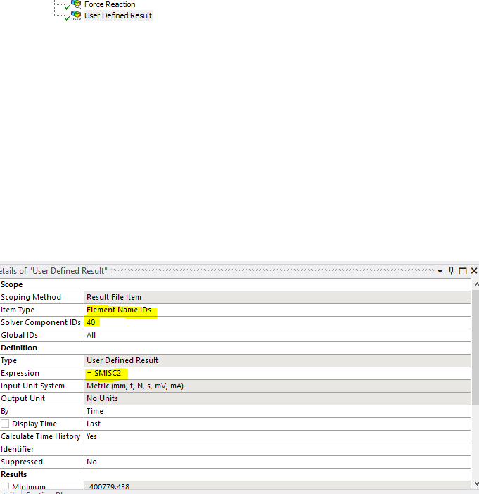
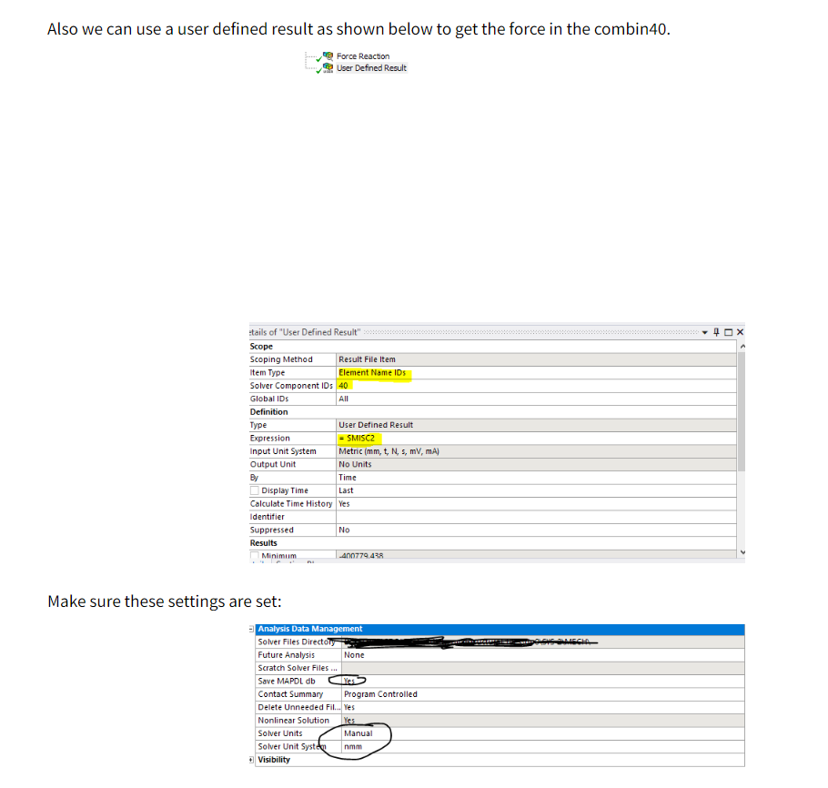
Do I need to add other function before defining the user defined result? How do I define spring on the item type?
May 5, 2022 at 10:50 ampeteroznewman
SubscriberI followed Erik's instructions for the two springs. The Item Type is a pull down.
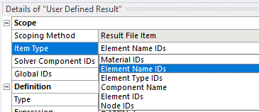 When I use 40, all the springs are included. Since I only have two springs, and the results plot Maximum and Minimum Values, I get two lines on the plot (after I uncheck the Average), so that works, but when you have 3 or more springs, you may want to select Element IDs.
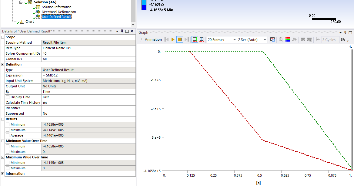 Here is the Force vs Min. Displacement.
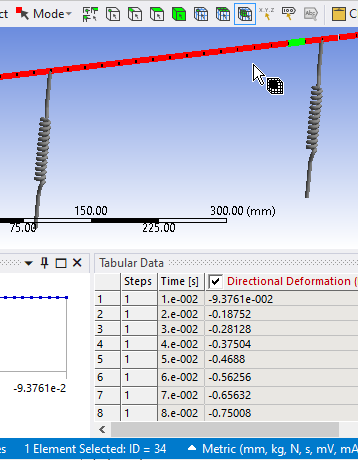
 I don't know how to obtain the spring element IDs in Mechanical, by graphical picking. You can see in the image below, I have the Element filter selected and can obtain the Element ID of the beam elements. I selected one beam element, highlighted in green and in the bottom edge of the screen, it shows that is element 34. But I can't pick the spring to find this out.
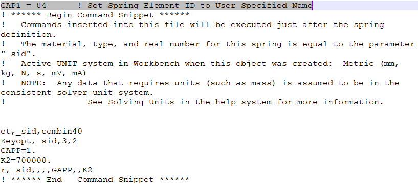
 In the Spring Details window, I can name the spring and I have given the springs two different names: Gap1 and Gap2.
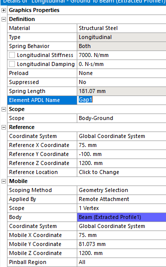 I don't know how to use the Gap1 APDL name with the User Defined Result.
I can open the ds.dat file and find the Element ID, which is a workaround for not finding it inside Mechanical.
 Viewing 28 reply threads
- The topic ‘How to model bilinear spring’ is closed to new replies.
Innovation SpaceTrending discussionsTop Contributors-
4678
-
1565
-
1386
-
1242
-
1021
Top Rated Tags© 2025 Copyright ANSYS, Inc. All rights reserved.
Ansys does not support the usage of unauthorized Ansys software. Please visit www.ansys.com to obtain an official distribution.
-


Ansys Assistant

Welcome to Ansys Assistant!
An AI-based virtual assistant for active Ansys Academic Customers. Please login using your university issued email address.
Hey there, you are quite inquisitive! You have hit your hourly question limit. Please retry after '10' minutes. For questions, please reach out to ansyslearn@ansys.com.
RETRY
