

-
-
September 26, 2020 at 3:11 pm
Balli
SubscriberHello everyone,
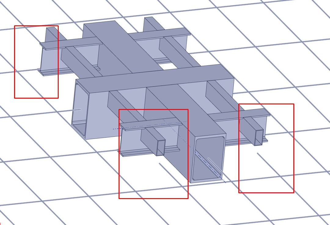
I have 8 platforms to calculate weight capacity. (Figure Model,model2 and model3) And my computer is not able to perform the analysis for shell models. Because of some platform models too big even I use symmetry. That's why I don't want to use shell models. I thought I can model beam and shell together. The general model will be beam and critical regions will be shell. I will use a rigid connection between them. But the problem is the center of gravity. When I transform the 3D to 1D lines are going different height because of the cross-sections. I'm moving them to the same level but at this time the model is changing. I mean the center of the solid model and the line are not going on the same height. If I move the solid to down, the geometry will change. Should I neglect that situation? It's really hard to explain what I'm trying to explain, but if you check the figure you'll see the red boxes that I want to highlight the regions. If I move the solid to down the connection will be changed. Is it acceptable? (Figure 1,2 and 3)
Or the second option is to use the original center of gravity for all of them. But how can I connect these beams that are located at different levels? (figure problem2.1, problem2.2)
September 28, 2020 at 11:18 amAniket Chavan
Forum ModeratorAnsys staff can not download images on the student portal, so if you want to reach a larger audience to get answers from, please insert the images inline.
-Aniket
How to access Ansys help links
Guidelines for Posting on Ansys Learning Forum
September 30, 2020 at 3:52 pmSubscriberThanks for your reply.
I didn't know that. So you may see the images below.


October 1, 2020 at 6:29 pmForum Moderatoryou can use contacts right? or do you want to share nodes? You will have to turn shell thickness effect on and use larger pinball radius.
October 1, 2020 at 7:02 pmSubscriberActually, that's not the problem.
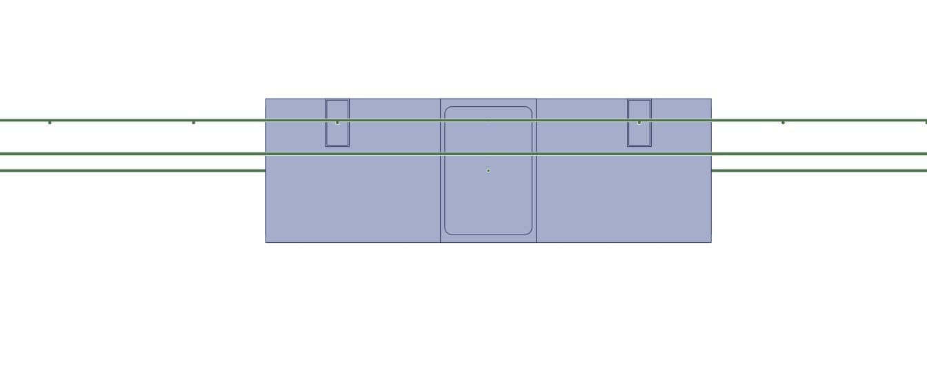
I want to use beam and shell elements together. I will connect them rigidly with fix joint. So there will not be a stress concentration at the connection point. But the problem is a centerline roblem between the center of the beam element and the center of the shell element. They are not in the same line as you may see the first and seventh picture above.
How should I deal with this? Should I move the shells in order to set the centers on the same line? Is this an acceptable approach?
Thanks for your reply.
October 2, 2020 at 1:05 pmpeteroznewman
SubscriberThe fixed joint can connect the end of the beam with the offset edge of the shell elements and transfer the load. Don't move any beams or shells, that would be changing the geometry you are trying to simulate.
October 3, 2020 at 6:47 amSubscriberGreat peter!
Thanks for your reply. I was so confused about whether changing the geometry or not. I am going to try this way.
Viewing 6 reply threads- The topic ‘How to model beam and shell together?’ is closed to new replies.
Innovation Space Trending discussions
 Top Contributors
-
peteroznewman
 5694
5694 -
scabo
 1891
1891 -
Dennis Chen
 1419
1419 -
javat33489
 1305
1305 -
Shyam Prasad V Atri
1021
Top Rated Tags
© 2026 Copyright ANSYS, Inc. All rights reserved.
Ansys does not support the usage of unauthorized Ansys software. Please visit www.ansys.com to obtain an official distribution.
-
Ansys Assistant will be unavailable on the Learning Forum starting January 30. An upgraded version is coming soon. We apologize for any inconvenience and appreciate your patience. Stay tuned for updates.


