-
-
October 20, 2021 at 12:57 pm
aroncolusso
SubscriberHi everyone, I am new and I am trying to model a problem using Ansys mechanical. Basically I am performing a transient thermal analysis followed by a transient structural analysis.
First of all I am importing a surface map of temperatures to a body, applying some boundary conditions in terms of insulation and convection and I am investigating 1) the temperature in the center of the body and 2) the time evolution of the temperature in the whole body.
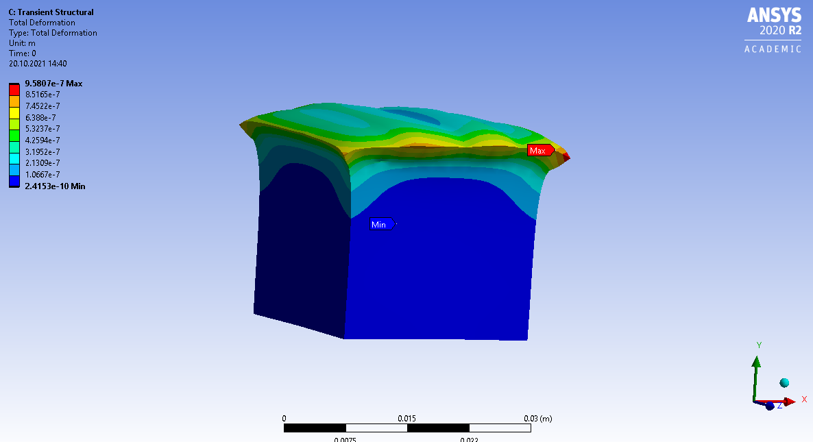
After that I am importing this temperature time evolution into the transient mechanical analysis. So far so good. The problem is that when I perform the simulation, the temperature is applied to the body at time 0 and the body deforms (expands) under this thermal load (picture 1). In my specific case however, the geometry I am importing is the already heated/deformed geometry and what I want to investigate is the contraction of the geometry as it cools down following the cooling process simulated in the first part.
Any idea if and how this could be implemented?
Thank you,
Aron
October 21, 2021 at 2:29 amOctober 21, 2021 at 6:26 amaroncolusso
SubscriberHi peteroznewman
Thank you very much for your reply.
I will try to implement your solution and get back to you if I have further doubts.
Thanks a lot
October 21, 2021 at 7:53 amaroncolusso
SubscriberHipeteroznewman
I edited the model, but still the deformation is applied at the first time instant and therefore I still can't simulate the contraction but I have an initial expansion.
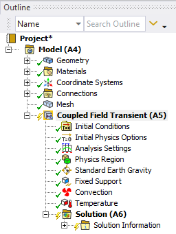
I attach the model three. Any suggestion?
thank you

October 21, 2021 at 10:56 ampeteroznewman
SubscriberThe idea is that you don't import any temperature data. You set this model up to compute that temperature as part of the heat up phase in step 1, then step 2 continues the simulation to cool down.
October 21, 2021 at 11:07 amaroncolusso
SubscriberOkay, I see what's happening here. The fact is that I need to work with a body that has a specific temperature at the beginning. Modelling the heating process is not part of my goals, and it would also not be feasible in terms of computing durations for my application.
What I want to achieve is starting at t=0 with a body/my imported geometry (in our example a very simple cube) apply a thermal map to one of the faces (composed of different temperature measurements at different coordinates) assuming the geometry I am starting with is the already deformed/expanded geometry and from there simulate the cool down phase to investigate how the structure shrinks/contracts. Maybe I was not very clear in my first question but the geometry I am importing in the workbench is the thermally expanded geometry.
Do you think that would be possible using Ansys?
I see that by changing the reference temperature value of the geometry I don't have an expansion anymore but only a contraction over time, but I am not very confident this is the result I am looking for. Also following this strategy I don't know how I could import my thermal map.
Thank you
October 21, 2021 at 7:12 pmpeteroznewman
SubscriberThe simple cube of material was heated up with boundary conditions that prevented thermal expansion on some faces, but not other faces. At the end of the heating process, there is a 3D distribution of temperature and stress in the cube and a deformed shape. You capture the deformed shape and the surface temperature, but you are not capturing the internal temperature distribution or the internal stress to begin the cool down phase. When you import a temperature on just the surface, what is the temperature on all the nodes in the center of the cube?
The benefit of doing the entire heating then cooling simulation in one model is that the full 3D temperature map and the internal state of stress through the whole cube as well as the deformed shape is all included so no information is lost when the cooling begins. While your interest is only the cool down phase, it may be simpler to build a model to do the heating up as well.
October 22, 2021 at 2:00 pmaroncolusso
SubscriberThanks again for your reply. I understood your nice explanation and I agree: by applying just a temperature distribution on one surface I am not considering the temperature distribution inside the body. To solve this first problem I performed a steady state thermal simulation, and by applying some boundary conditions I can obtain the temperature distribution on all nodes. Let's assume this distribution is "good enough" for my application. I then imported this temperature distribution in a coupled field simulation and defined it as initial condition. Again I apply some boundary conditions in both the thermal and mechanical field (fixed cube base + convection on the sides and a temperature constrain on the base). The problem that I still have and that I would also have with your last suggested strategy is that the geometry I am importing in my simulations is the one obtained with that temperature distribution. That geometry is already hot and deformed, and I don't know the standard geometry. This means that if I would follow your proposed strategy my part would undergo additional thermal expansion and the result I will obtain is not the one I am looking for.
With what I tried so far I managed to obtain the thermal distribution in the inside of the body as said earlier in the message. The problem is once again that even if I apply it as being the initial condition, it will be applied in the simulation time instant "0+" (let's call it that way, where I mean the first simulation instant). Once again the result is that the geometry is treated as being cold and undeformed, and therefore at the time instant 0+ the geometry undergoes a thermal expansion, and if the simulation is performed for a long enough period, and the part cools down completely, the shape gets back to a perfect cubic shape without residual strains, whereas I expect a contracted shape for t=infinity.
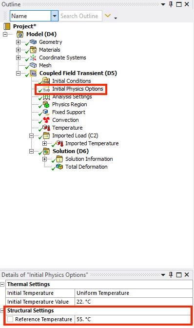
In the project tree, under "Initial Physics Options" I found the "Reference Temperature" under structural settings. By applying a high temperature value (I picked the maximum temperature of my superficial temperature distribution, which I assume to be the highest temperature in my body) I have a thermal contraction as a result. My questions is: how wrong will my result be in the end? Because as far as I understand my thermal distribution inside the body is exactly what I should define under "Reference Temperature".
Thank you very much for your help, and sorry for my many questions, this is my first Ansys experience and I am still exploring all the many available settings.

October 22, 2021 at 10:48 pmpeteroznewman
SubscriberI assumed you would know the initial shape of the cube. My suggestion was to have a complete simulation starting with the initial shape of the cube and let it expand as it heats up and contract as it cools down.
Ansys has a chapter in the Help system on Inverse Solving. That is where you take the final deformed shape and solve for the initial shape. Open Ansys help then copy/paste this URL into the Browser running help.
https://ansyshelp.ansys.com/account/secured?returnurl=/Views/Secured/corp/v212/en/ans_str/strnonlininversesol.html?q=inverse%20solution
I haven't used this personally, I just know about it. Not sure how useful it may be for your problem.
The Reference Temperature is the anchor for the Secant values of a property like the CTE. The initial temperature defines what happens at Time=0. I notice that there is a non-uniform setting. I haven't tried that myself.
 Viewing 8 reply threads
- The topic ‘How to model a thermal contraction problem?’ is closed to new replies.
Ansys Innovation SpaceTrending discussionsTop Contributors-
3597
-
1283
-
1107
-
1068
-
978
Top Rated Tags© 2025 Copyright ANSYS, Inc. All rights reserved.
Ansys does not support the usage of unauthorized Ansys software. Please visit www.ansys.com to obtain an official distribution.
-


Ansys Assistant

Welcome to Ansys Assistant!
An AI-based virtual assistant for active Ansys Academic Customers. Please login using your university issued email address.
Hey there, you are quite inquisitive! You have hit your hourly question limit. Please retry after '10' minutes. For questions, please reach out to ansyslearn@ansys.com.
RETRY


