-
-
May 1, 2024 at 8:12 am
Chihiro Komatsu
Subscriber -
May 1, 2024 at 11:08 am
peteroznewman
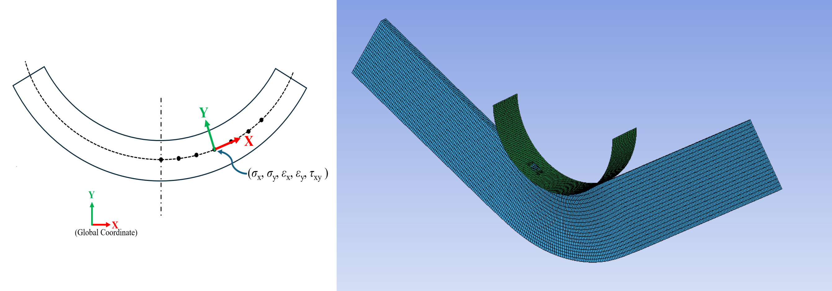
SubscriberCreate a Cylindrical Coordinate System with the origin at the center of the cylinder and the Z axis along the axis of the cylinder. Plot Normal Stress or Strain and set the coordinate system to the Cylindrical Coordinate System. The X axis is Radial and the Y axis is Tangential so I suggest you relabel your figure to match how Ansys reports the stress components in a cylindrical coordinate system.
-
Viewing 1 reply thread
- The topic ‘How to measure strain and stress in a coordinate system along the material axis’ is closed to new replies.
Innovation Space


Trending discussions


Top Contributors


-
4597
-
1495
-
1386
-
1209
-
1021
Top Rated Tags


© 2025 Copyright ANSYS, Inc. All rights reserved.
Ansys does not support the usage of unauthorized Ansys software. Please visit www.ansys.com to obtain an official distribution.


