TAGGED: convergence-issue, laminar-flow, laminar-pipe-flow
-
-
November 21, 2023 at 7:32 am
Tomomi
SubscriberHello everyone,
I'm a master's student and relatively new to Ansys Fluent. Since September, I have been learning how to use it from scratch by myself.
I'm writing this post because I'm struggling to let my simulation for an abrupt expansion pipe converge.
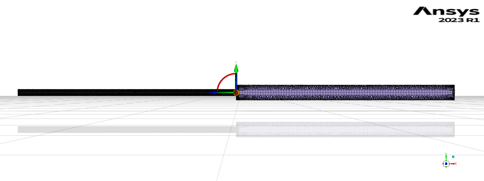
The geometry of my abrupt expansion pipe is like this:

Mesh qualities:
- Minimum Orthogonal Quality: 0.16
- Maximum skewness: 0.39
(According to the manual, these qualities seem to be okay, though it's not that good.)The setup in Fluent that I did is the following:
Solver setting in General:
- Type: Pressure-Based
- Velocity Formulation: Absolute
- Time: SteadySince the flow is laminar(Re for the thin pipe = 2000, Re for the thick pipe = 666), I choose the Laminar model.
Boundary conditions:
- Inlet velocity = 0.172 m/s
- Outlet pressure: Gauge pressure = 0 PaWhen I set smaller inlet velocity (0.001 m/s, 0.003 m/s, 0.005 m/s, 0.011 m/s, 0.021 m/s, 0.043 m/s), the simulation successfully converged. However, with a larger inlet velocity like this time (0.172 m/s), the simulation no longer converges...
I tried the following solutions, but none worked well:
- Increase the number of iterations
- Change fluid time scale
- Change relaxation factorsI have been trying my best to think about possible solutions by myself, but unfortunately, I have not succeeded. I would appreciate it if some of you could give me possible suggestions.
-
November 21, 2023 at 10:33 am
Rob
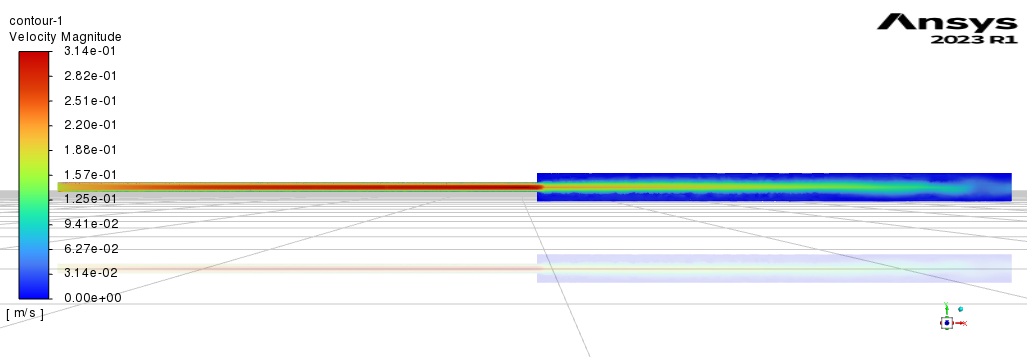
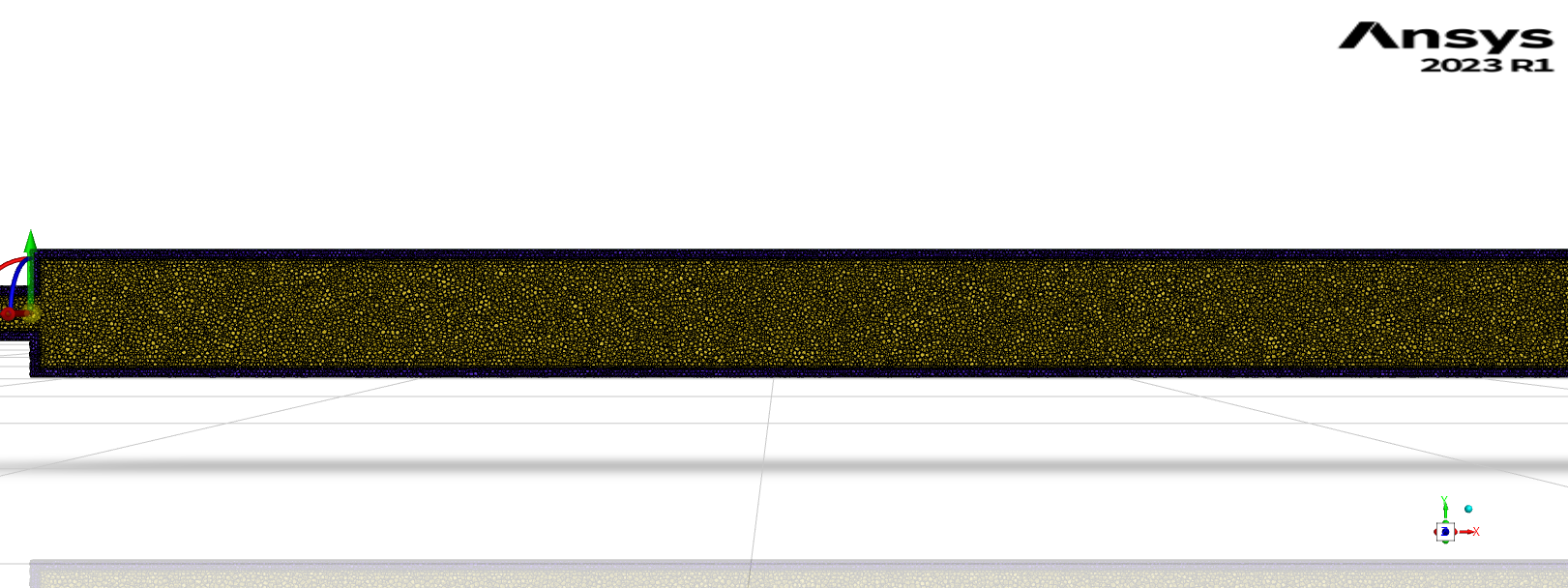
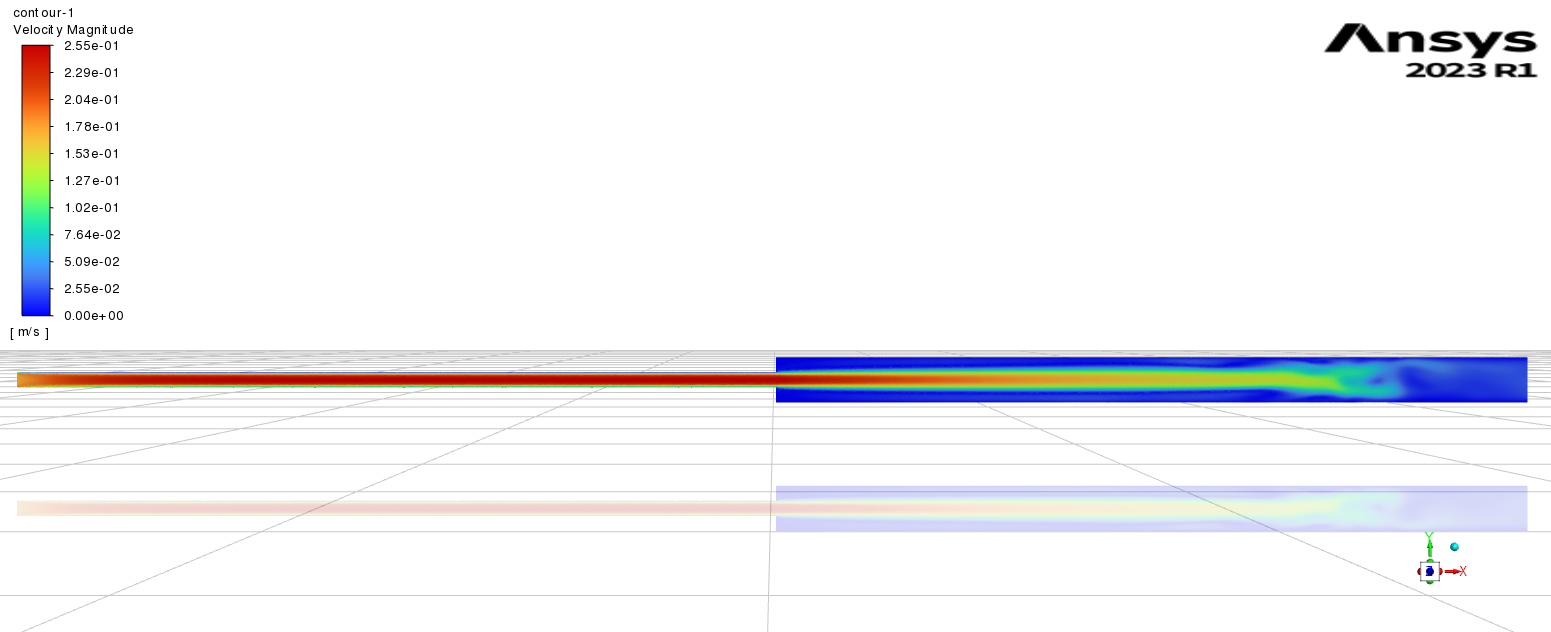
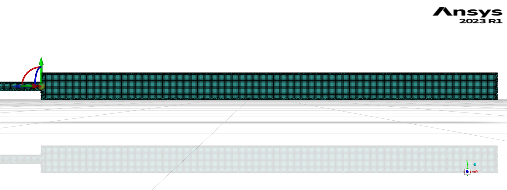
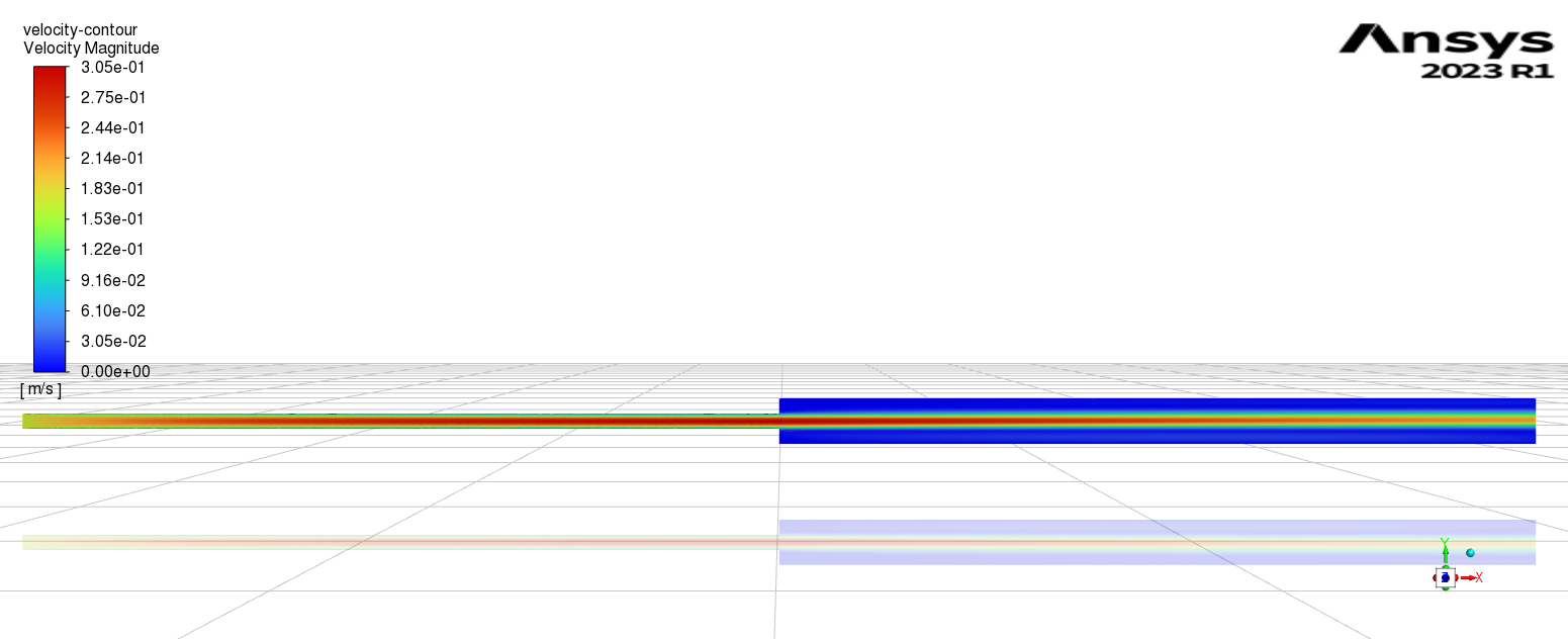
Forum ModeratorPlease can you post a screen shot of the mesh? Centre plane please. Also a velocity contour.
-
November 21, 2023 at 11:50 am
-
November 21, 2023 at 1:28 pm
Rob
Forum ModeratorYou don't need to include the metal bit unless you really want to see the temperature. Have a look at Fluent's wall boundary options to see what's possible.
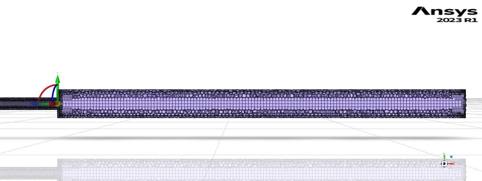
Looking at the mesh & contour. The "jet" is diffusing down the coarse mesh in the middle of the expansion. In CFD we mesh to both the geometry and the flow: we need to capture the domain shape, but also resolve the flow gradients. In this case you've refined the wall but not the core where the flow is getting interesting. Remesh with a pure poly mesh and have a look at Bodies of Influence: it'll be covered in the Learning modules on here or from Help in Fluent Meshing.
-
November 22, 2023 at 10:57 am
Tomomi
SubscriberHi Rob, Thank you very much for your detailed advice. I deeply appreciate your help.
I watched the video for BOI and was trying to adopt BOI, but I couldn't find the same one in Ansys Fluent Meshing. When making mesh, I always use Ansys Fluent Meshing. In terms of functions, is BOI in Design Modeler similar to Local Meshing in Ansys Fluent Meshing? Which do you recommend me to use for meshing, Design Modeler or Ansys Fluent Meshing?
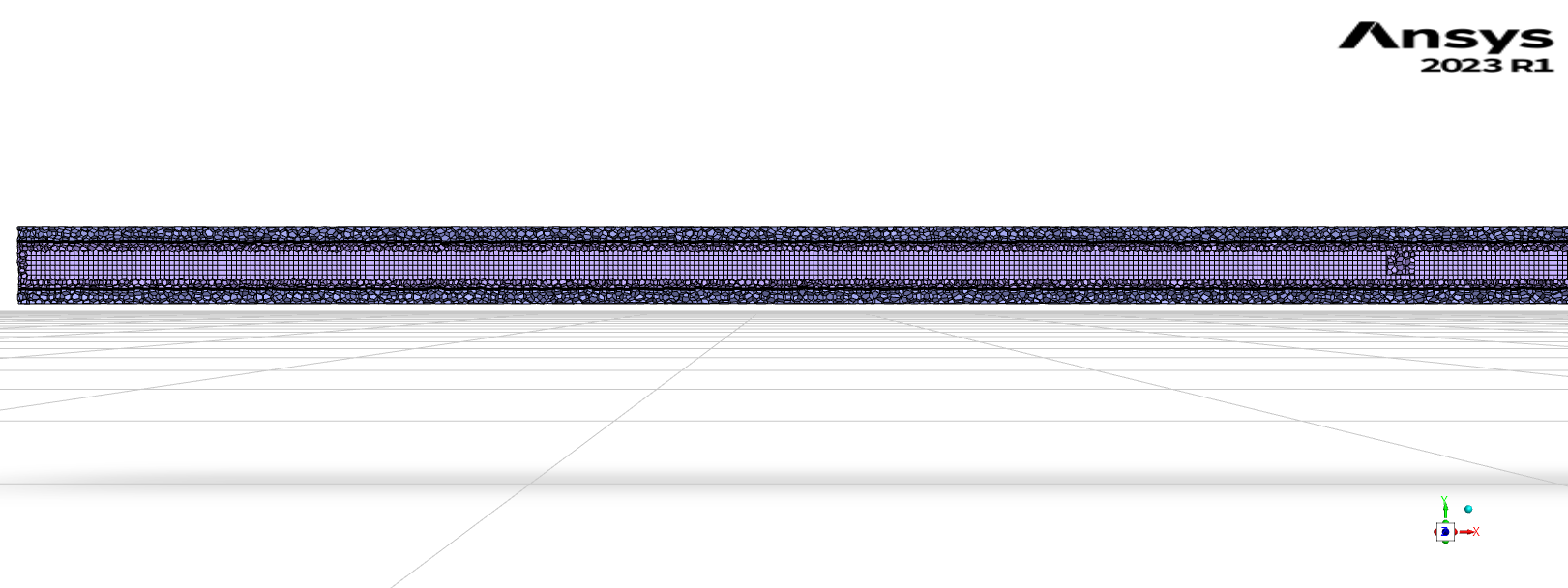
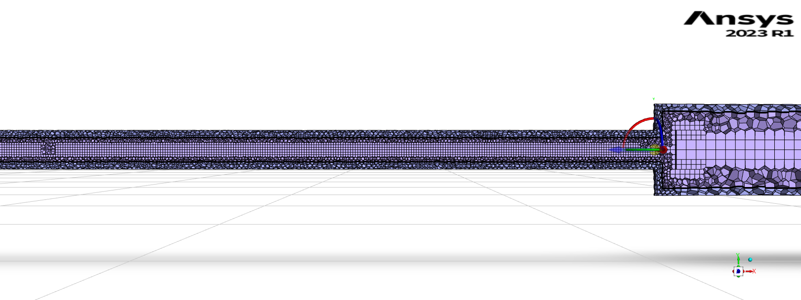
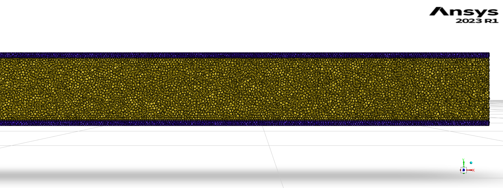
So, before removing the metal and adopting BOI, for the first simple attempt, I tried to improve my mesh by changing the mesh size and mesh shape. But it didn't work. The screenshots of the mesh and the velocity contour are below.
When looking at the meshes, I thought that this mesh was better than the previous one, but the result said that the mesh quality got worse (Minimum Orthogonal Quality = 0.05, Maximum skewness = 0.43). I couldn't understand why. Is this mesh not good enough to analyze the flow in this pipe?
I apologize for disturbing you with so many basic questions, but I would appreciate it if you could give me some suggestions.
-
November 22, 2023 at 12:08 pm
Rob
Forum ModeratorThat looks better - you're aiming to avoid coarse mesh around the jet as you need to resolve the gradients. Now look at the region the jet breaks down in more detail. You may find a mix of contours and vectors on multiple planes will be needed to work out what's going on.
Cell quality of 0.05 isn't ideal but is probably OK. Remember cell quality reports on how squashed cells are; you need to manually review the mesh quality once the model has run.
You're still meshing the solid part - why?
-
November 24, 2023 at 12:40 pm
Tomomi
SubscriberHi Rob, thank you again for your prompt feedback. I cannot thank you enough for your help.
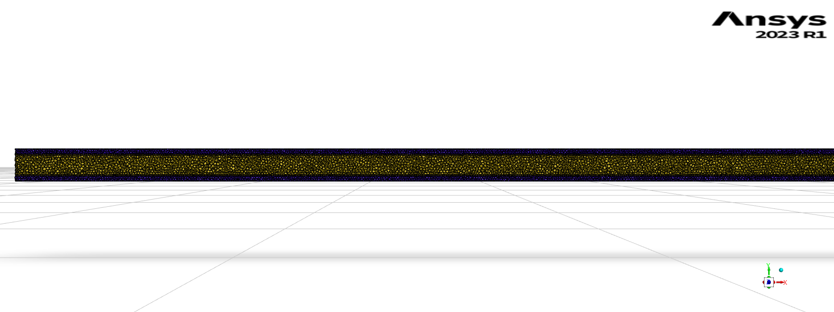
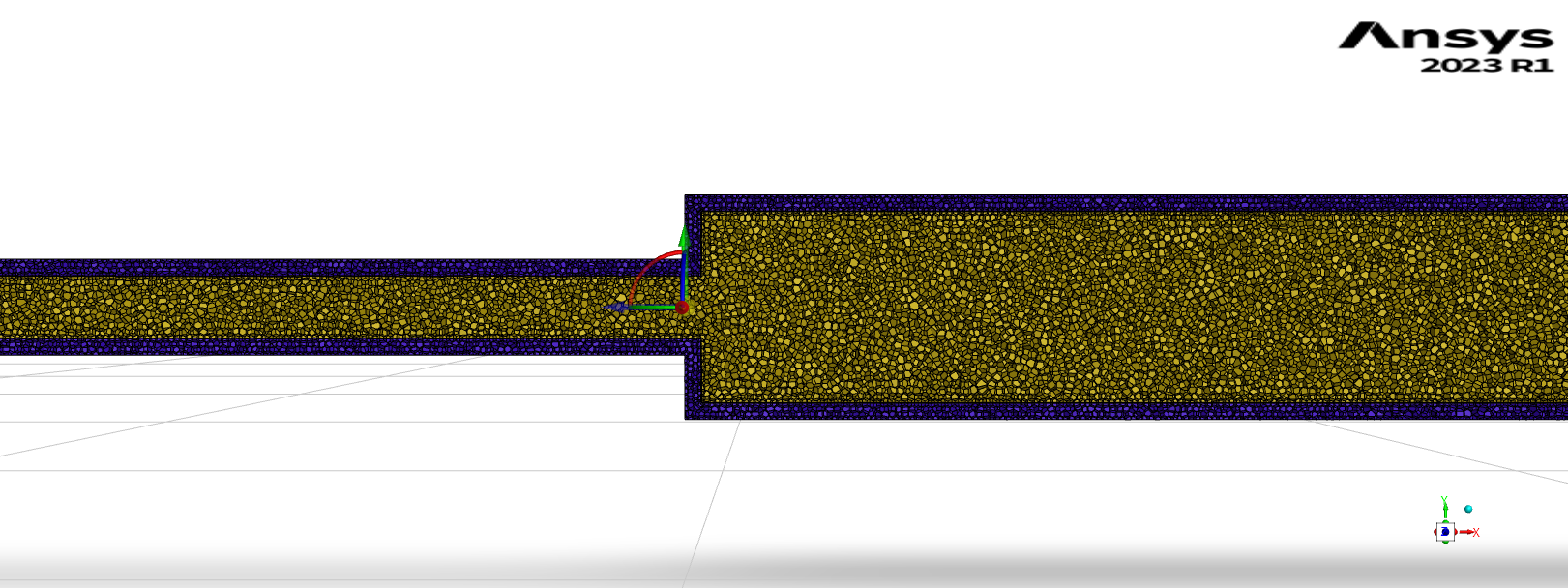
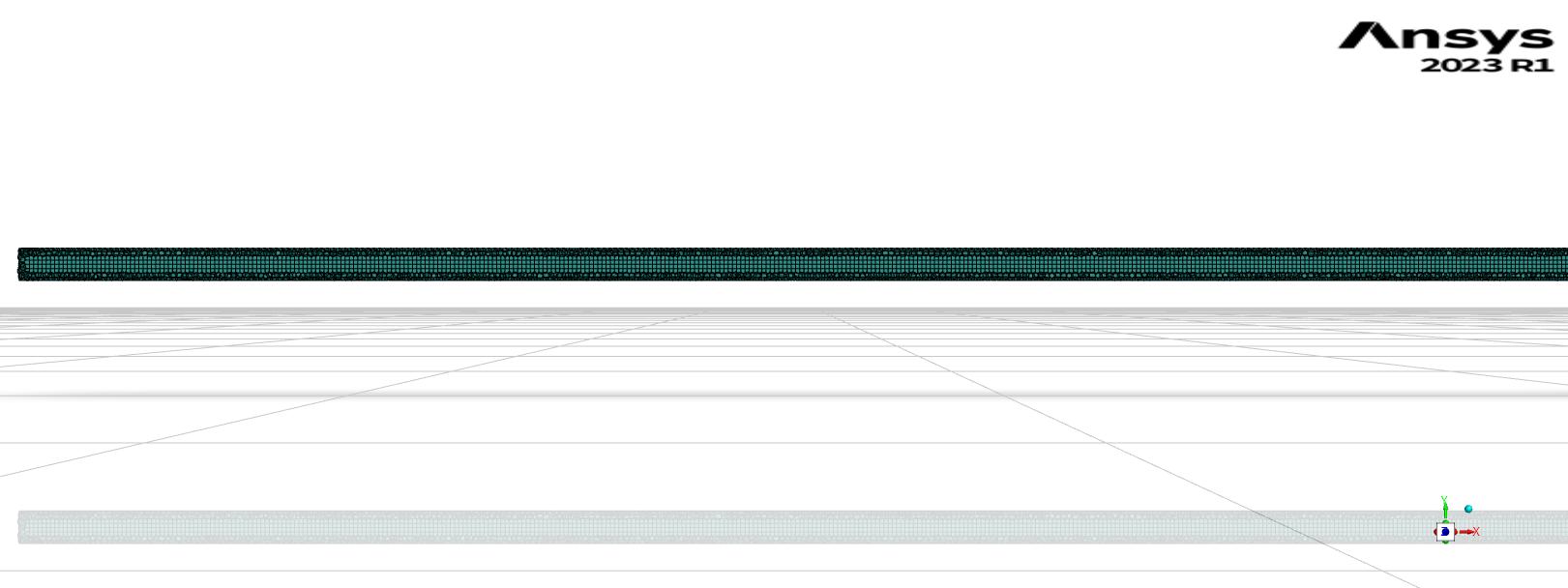
I removed the solid part and did meshing again. This time, the simulation successfully converged.
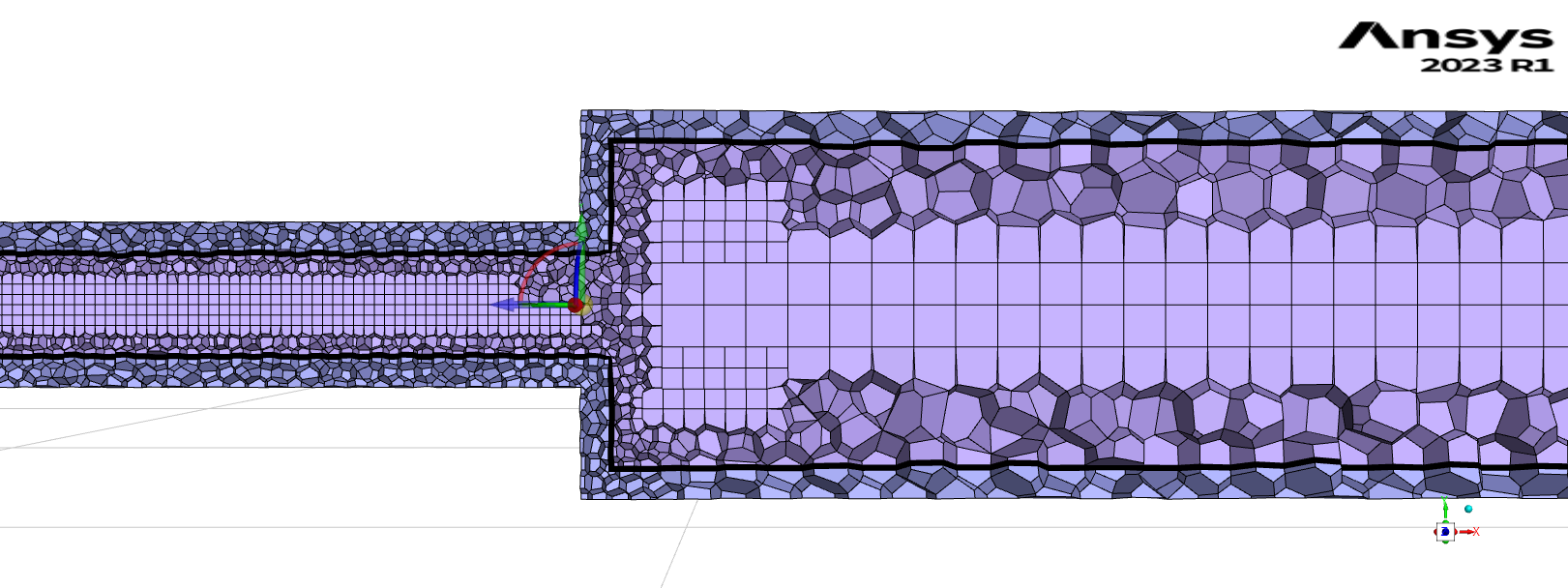
FYI, the Minimum Orthogonal Quality was 0.06, and the Maximum skewness was 0.23. What do you think about these mesh qualities? I've attached the screenshots below.
I have one more question. When I need to mesh the solid part as well (like I did before), how can I improve my mesh? In that case, is it better to do Local Meshing?
-
November 24, 2023 at 12:51 pm
Rob
Forum ModeratorThat looks more reasonable. Zoom in on the jet and replot the velocity contour with node values off. That'll help show if you have sufficient resolution of the jet, no need to post images, it's for your learning.
I'm not sure if you need the solid region. Unless it's deforming I'd use a thin wall but make it "thick" using the Fluent boundary options. If you do want it, set as solid in Fluent Meshing and let the meshing tools do the work. I'm not as familiar with the functions so can't really advise further.
-
November 27, 2023 at 4:06 pm
Tomomi
SubscriberHi Rob, I'm sorry for the late reply.
Thank you again for your prompt feedback. I learned a lot from your advice. Please accept my deepest thanks.
-
-
- The topic ‘How to make my simulation converge?’ is closed to new replies.


-
4833
-
1587
-
1386
-
1242
-
1021

© 2026 Copyright ANSYS, Inc. All rights reserved.

