-
-
July 21, 2021 at 6:19 am
VigneshV18
SubscriberI have an hollow cuboid shaped object with ~80 holes on top of it. This object is placed inside an enclosure. I have named two opposite faces of the enclosure as inlet and outlet and I want to simulate air flow in which, the air flow starts from the inlet and enters into the object through the holes before it exits via the outlet face of the enclosure.
July 21, 2021 at 6:38 amAmine Ben Hadj Ali
Ansys EmployeeI hope fluid volume extraction was fine. Can you share with us plot of pathlines? Moreover can you share with us a screenshot of boundary conditions from Fluent panel?
July 21, 2021 at 7:06 amVigneshV18
SubscriberHi DrAmine,
Yes, I performed boolean operation to create a proper fluid domain. Fluid domain is present for the air to flow into the object through the holes. However, it's not happening so. I am doing the simulation on a different PC and I need sometime to post the screenshot of the result here. i shall post the screenshot of pathlines and boundary conditions as soon as i get the results.
Thank you.
July 21, 2021 at 7:15 amAmine Ben Hadj Ali
Ansys EmployeeWelcome!
July 21, 2021 at 8:12 amVigneshV18
SubscriberHi DrAmine Please find the attached screenshot of the boundary condition and the flowpath lines. the flow path lines are not properly exiting via the outlet because, i had to change the control values as the continuity was not converging and i was receiving floatpoint error.
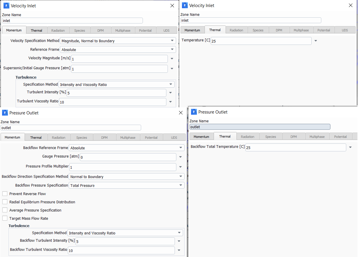

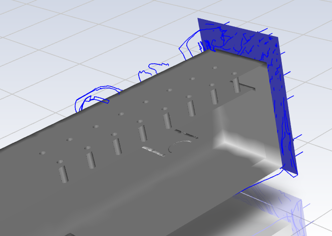
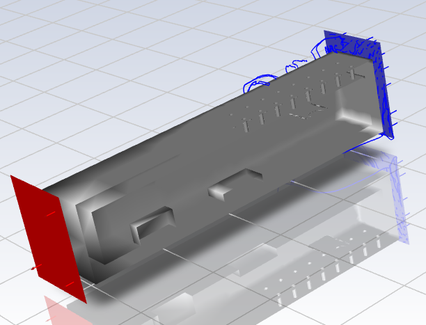
could you advise me the proper BCs to be used for this problem.
Thank you!
July 21, 2021 at 10:56 amRob
Forum ModeratorYou need to expand the outer domain as the boundaries are too close to the object of interest. There's also the question of why flow will pass into the enclosure rather than just flow around it.
July 21, 2021 at 11:53 amVigneshV18
SubscriberHi Rob Previously, I used a larger outer domain and the result was same. Just to reduce the number of elements in meshing I reduced it's size. However, I shall try to repeat the simulation again with a larger domain.
To answer your next question, I am not sure of why would it pass into the enclosure. But, I am pretty sure air does flow inside the enclosure through these holes. For example, consider the case of a gas sensor. Gas sensors of any principle (thermal conductivity, NDIR, photo-acoustic), the sensing element is placed inside an enclosure with small holes or porous membrane top of it for air to pass inside. The sensor reads correct data only if outside air pass through these holes/membranes into the enclosure right. I am not sure of the exact phenomena behind it though. that's the reason, i am unable to provide proper boundary conditions in the simulation.
Could you explain me whether is it possible to run the simulation and get the results as I am expecting?
Thank you.
July 21, 2021 at 12:09 pmAmine Ben Hadj Ali
Ansys EmployeeI am interested to see the 2D BC's named interior in your case: can you mass flow rate them? Can you highlight them and share panel. Flow will into the holes if there is favorable pressure gradient.
July 21, 2021 at 12:35 pmRob
Forum ModeratorFluid will flow if there's a pressure gradient, but also a concentration gradient will drive diffusion. What mechanism are gas detectors designed to work with?
July 21, 2021 at 12:49 pmVigneshV18
SubscriberHi DrAmine,
I guess, you are asking for the model of interior? please have a look at the below snapshot. This part is mentioned as "interior-solid(interior, id=2)" under the boundary condition "internal".
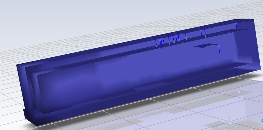 when I tried to edit it, the dialogue box does not have any option. please have a look into it.
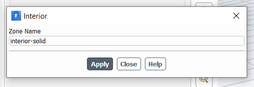 Hi Rob
From what you explained, I can say that concentration gradient is what drives the air to flow in case of gas sensors.
July 21, 2021 at 1:14 pmRob
Forum ModeratorCan you post a contour plot of velocity on a plane through the model?
July 21, 2021 at 2:37 pmVigneshV18
SubscriberHi Rob I tried changing the inlet and outlet face on the outer domain, like the inlet is directly above the holes. in this case, i see that air flow is going into the enclosure. please have a look into the below screenshot.
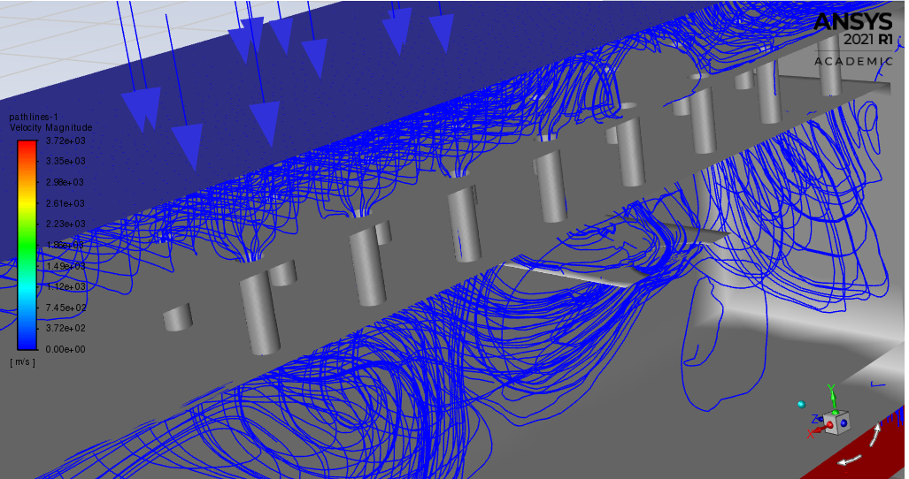
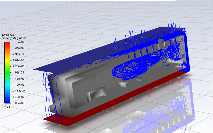 And also please find the screenshot of velocity as contour on the symmetry plane.
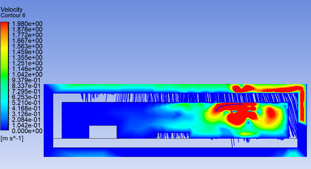 My doubt is, does air only travel in a straight line when not disturbed?
July 21, 2021 at 3:07 pmRob
Forum ModeratorAs there's no clear route for the air to leave the box (all the holes are subject to the inlet air condition) the above looks about right. Check the mesh resolution as those contours don't look great. I suspect convergence isn't overly good either.
Fluids also follow Newton's Laws of motion. So if there's no reason (force) to change direction they won't.
July 21, 2021 at 3:27 pmVigneshV18
Subscriberunderstood. I shall work on the mesh resolution and convergence next.
thank you for the support!
Viewing 13 reply threads- The topic ‘How to make air flow from inlet into an object with holes’ is closed to new replies.
Innovation SpaceTrending discussionsTop Contributors-
5074
-
1823
-
1387
-
1248
-
1021
Top Rated Tags© 2026 Copyright ANSYS, Inc. All rights reserved.
Ansys does not support the usage of unauthorized Ansys software. Please visit www.ansys.com to obtain an official distribution.
-
The Ansys Learning Forum is a public forum. You are prohibited from providing (i) information that is confidential to You, your employer, or any third party, (ii) Personal Data or individually identifiable health information, (iii) any information that is U.S. Government Classified, Controlled Unclassified Information, International Traffic in Arms Regulators (ITAR) or Export Administration Regulators (EAR) controlled or otherwise have been determined by the United States Government or by a foreign government to require protection against unauthorized disclosure for reasons of national security, or (iv) topics or information restricted by the People's Republic of China data protection and privacy laws.


