3D Design

3D Design

Topics related to Ansys Discovery and Ansys SpaceClaim.

How to get instersection Points made by two line bodies going through each other

    • Suhi Suhaas
      Subscriber

      I have line bodies going through each other. There are many locations where I guess software detected the intersection point and marked that point. But there are also other locations where I can't see intersection points. I just wanna know how to get those intersection points.


    • mjmiddle
      Ansys Employee

      It lools like you are using DesignModeler. Can you right click on the line body in the Outine to show the errors?

      If you were using SpaceClaim, you would normally use "Prepare > Imprint." There is a tolerance value in the options panel for this tool that you may need to adjust. Or use the "split curve" in sketch tools in 3D sketch mode:

      In DesignModeler, there is no simple way to split line bodies by an intersection. I did it by first using a Boolean feature set to "Imprint Faces." For the target and tool bodies, it won't let you select them from the model viewer. You must select them from the Outline. Set "Preserve tool bodies" to yes.

      This will split the line body into two edges within one body. You can turn on vertex display or use edge selection to confirm.

      Now use "Concept > Lines from edges" set to "add frozen." Select one edge on the split body. Use another "lines from edges" operation for the other edge.

      Now you can use a delete body operation to delete the original line body. You'll have to set the cross sections on the two new lines bodies.


    • Suhi Suhaas
      Subscriber


      Actually, When I made those line bodies go through each other, the software automatically created an intersection point without any requirement of meddling with tools. I have used those points to create horizontal braces as you can see in the above images. I am just wondering why the intersection is not getting created in all locations. By the way, I dont want to split line bodies. I just want intersection points. Once I get them I can create new line bodies from those points to outer members. But anyway I will get back to you once I try boolean. BTW thanks a lot for replying


    • mjmiddle
      Ansys Employee

      I don't know any operaton that is making vertices automatically. Maybe it is done with some import types and certain options in the Details for the import feature. What operation is creating the vertex automatically for you? The software may be expecting a very exact intersection. There may be be some small gaps between lines where you think it intersects. If you made the lines in sketched then maybe you have sketched under different planes. 

    • Suhi Suhaas
      Subscriber

      My project is actually on a lattice tower.


      I have a detailed plan of the lattice and I just went on to create line bodies based on that drawing. I could able to create X-Bracings using various points and projection of points depending on the requirement. 


      As you can see in this image, I didn't have to do anything to get that point. It was just there when I created those line bodies going through each. But I just dont why those points were not created at all at many other locations. Am I missing something?

    • mjmiddle
      Ansys Employee

      If you are using "Concept > Lines from Points" and assuming you have points at the intersection locations that you are selectiing, you could set to "Add Frozen":

      If you selected points father away during the "Concept > Lines from Points" feature, then you would not have edges with boundaries at the intersection location.

      Where are these points coming from? Did you import? Did you create in a sketch? Did you use the "Create > Point" as "Construction point" using "From coordinates file" or "Manual input?" 

    • Suhi Suhaas
      Subscriber


      Sorry. Now I remember.


      This is the plan actually. And I had to project the points onto the main members or main legs. After, creating those projection points, I went on to create X bracings or Cross Bracings. After this step, I had to create horizontal bracings. To create them I took half of each length, for example, 4000mm/2 = 2000mm, and created points manually to project onto the main member. Now, after projection and I created lines using “LINES FROM POINTS” to create HORIZONTAL bracings. Then, those intersection points of all bracings were not created automatically. I used Projection tool to create those points.


    • Suhi Suhaas
      Subscriber


      Errors :
      1. An internal solution magnitude limit was exceeded. Please check your Environment for inappropriate load values or insufficient supports.  Please see the Troubleshooting section of the Help System for more information.

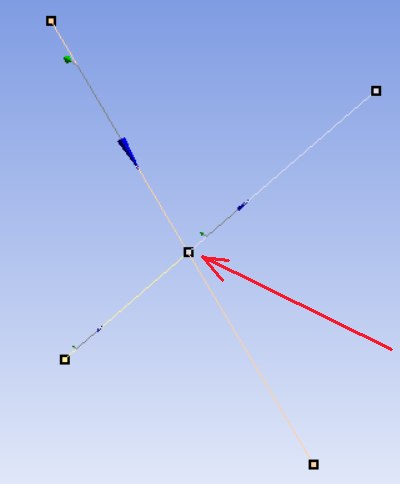
      2. An internal solution magnitude limit was exceeded. (Node Number 113, Body Level 3.6, DOF UX) Please check your Environment for inappropriate load values or insufficient supports.  You may select the offending object and/or geometry via RMB on this warning in the Messages window.  Please see the Troubleshooting section of the Help System for more information.

      Warnings :
      1. Solver pivot warnings or errors have been encountered during the solution.  This is usually a result of an ill conditioned matrix possibly due to unreasonable material properties, an under constrained model, or contact related issues.  Check results carefully.

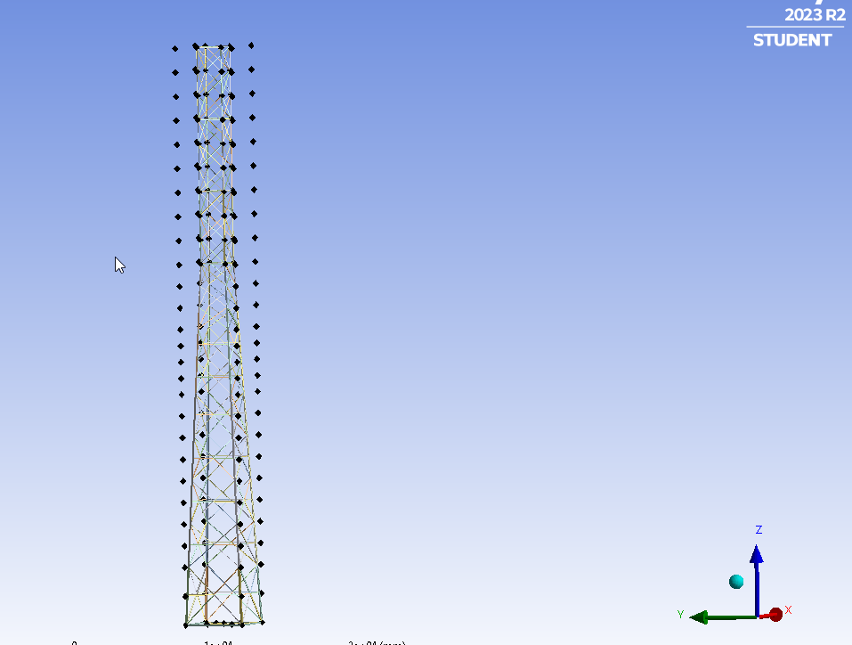
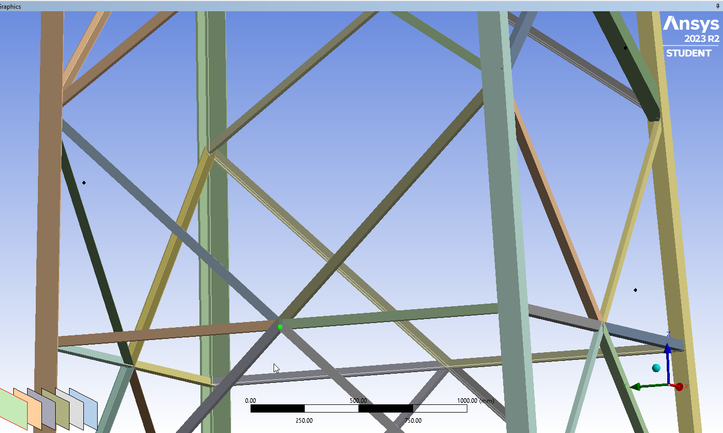
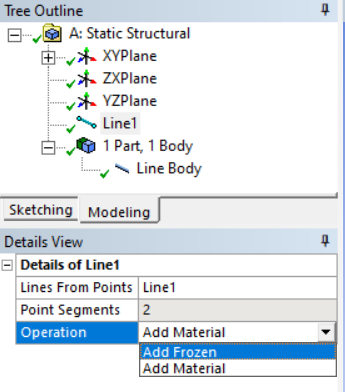
      2. Line bodies with type set to Link/Truss or Cable may not be able to solve if Large Deflection is turned off in the Analysis Settings for the model.

      3. One or more objects may have lost some scoping attachments during the geometry update. You can identify these tree objects by activating the Scoping Wizard in the Selection Toolbar, or by filtering the tree using the Scoping option set to Partial.


      By the way, thanks for being patient with me. I have these issues and been struggling since weeks. Can you help me how to solve these errors regarding Truss elements.


    • mjmiddle
      Ansys Employee

      It sounds like you are moving on to different topics, so you should submit a new post(s). If you have rigid body motion, make sure your beams are connected either as a shared multibody part in DM or joints or MPC contacts in Mechanical.

    • Suhi Suhaas
      Subscriber
Viewing 9 reply threads
  • You must be logged in to reply to this topic.