-
-
December 28, 2021 at 11:32 pm
jccubi
SubscriberHi everyone,
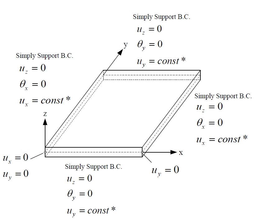
I am trying to set the boundary conditions of a plate under in plane axial load as shown in the following picture. The plate is modeled with shell elements and in the picture the symbol * means coupled DOFs. I would appreciate someone could help me to understand how to get in Workbench the boundary conditions Ux = const* and Uy=const* as shown in the picture. Than you in advance.
December 29, 2021 at 6:26 amRameez_ul_Haq
Subscriber,see this discussion:
December 29, 2021 at 6:26 amVinayak Vipradas
Ansys Employee
December 29, 2021 at 3:34 pmpeteroznewman
SubscriberLook at the left edge. One node on the left edge is at the origin. That has Ux = 0, therefore, all the nodes on the left edge will have Ux = 0, so that is an easy one.
Look at the bottom edge. One node on the bottom edge is at the origin. That has Uy = 0, therefore, all the nodes on the bottom edge will have Uy = 0, so that is another easy one. Just use a Displacement B.C. to accomplish these.
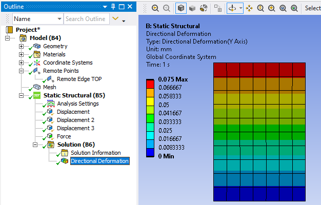
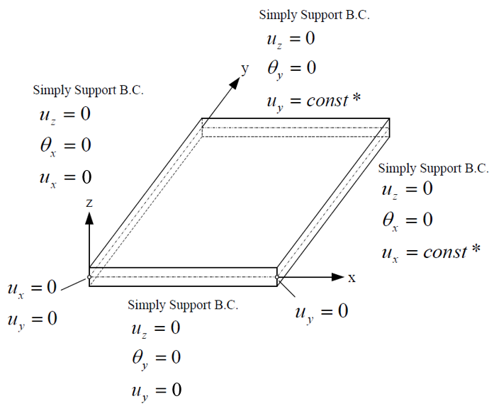 In Mechanical, create a Remote Point and set the Behavior to Coupled. In the image below, I have created a Remote Point for the top edge.
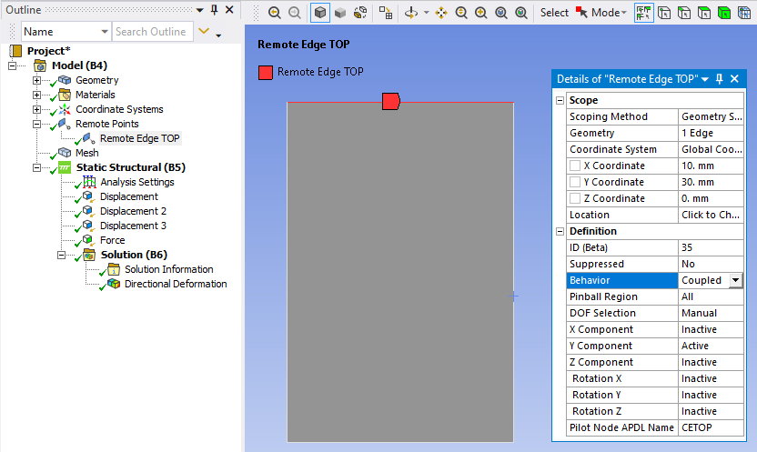 Do the same for the right edge, but where I left the Y component as the only Active DOF for the top edge, you would use the X Component as the only Active DOF for the right edge.
I didn't bother to constrain the rotational DOF, though you can, because there are no loads that will cause rotation. I applied an axial load on just the corner to illustrate the effect of the Coupled Remote Point.
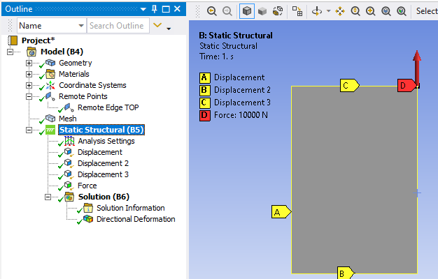 The Coupled Remote Point keeps the top edge parallel to the X axis.
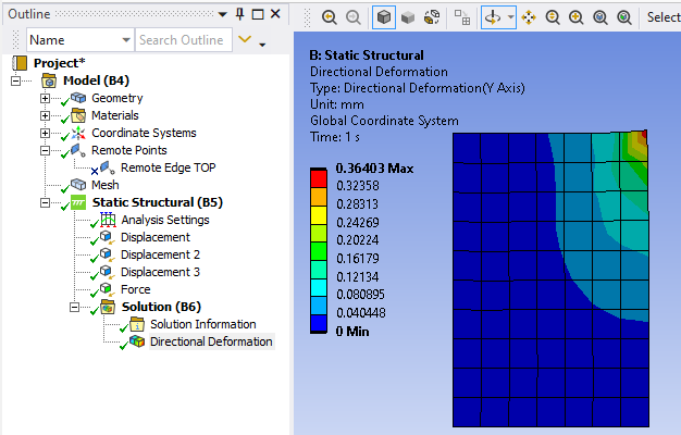
 If I suppress the Remote Point, the force causes that corner to get pulled forward more than the rest of the top edge.
 December 29, 2021 at 7:20 pm
jccubi
SubscriberThank to viviprada and an special thank to peteroznewman for such comprehensive explanation (example included) that helped me to fully unsderstand the concept. Your allways professional help is really appreciated.
December 30, 2021 at 12:56 pmRameez_ul_Haq
Subscriber,well I tried checking again what would be the difference between coupled behavior of a remote point and rigid behavior of a remote point. Apparently, I don't see any. There is option to manually select the 'DOF selection' for both of them. Rigid means the nodes cannot have a relative motion between each other in any of the active DOFs, and I guess coupled also means the same. Because it literally says COUPLED. If there is, I would be glad to hear it out, sir.
Secondly, do you think there is a need to actually have 'DOF Selection' option for Deformable behavior? I mean there is no increased stiffness at all on the scoped geometry, so esentially all the nodes can behave independtly in each DOF. So what what happen if I inactivate any of the DOF for deformable behavior?
December 30, 2021 at 6:38 pmpeteroznewman
SubscriberI see a large difference when I change the Remote Point named Remote Edge TOP to Rigid instead of Coupled.
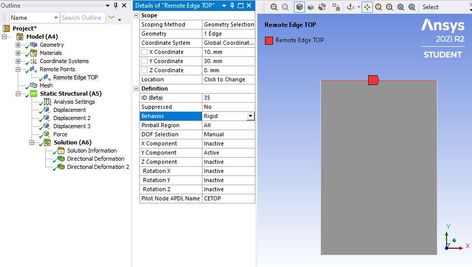 Here are the results, which are very different than the Coupled Behavior shown previously.
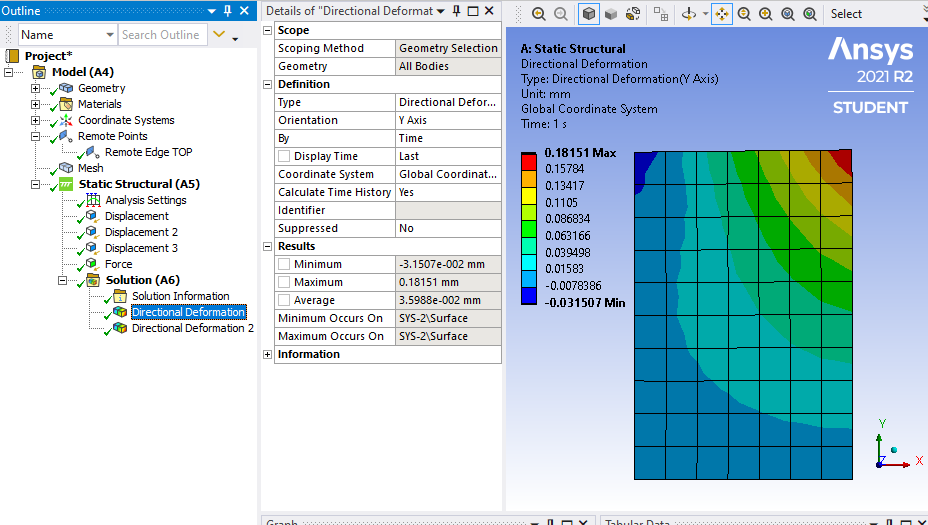 There may be benefits to setting some DOF inactive on a Deformable Remote Point. I don't think it makes a difference on this example.
December 30, 2021 at 7:07 pmRameez_ul_Haq
Subscriber,ohh. okay. Now I understand. So basically the distance between the nodes scoped to rigid behavior should remain equal but these nodes can have not equal translational motion. While for coupled, they need to have the same translational motion. Great illustration with example, sir.
Now, does the coupled behavior add some extra rigidity between the nodes or not?
Secondly, if I apply rigid behavior to some scoped nodes with a remote point, then we already know that distance between these nodes should always remain same. What about rotation? Can these nodes have independent rotations?
December 30, 2021 at 7:18 pmpeteroznewman
SubscriberYes, the coupled remote point is adding rigidity. Look at the displacement with and without it, there is a huge increase in stiffness as evidence by the huge change in displacement for the same force.
Secondly, nodes can have independent rotation if you leave that DOF inactive.
Viewing 8 reply threads- The topic ‘How to get coupled DOFs?’ is closed to new replies.
Innovation SpaceTrending discussionsTop Contributors-
4693
-
1565
-
1386
-
1242
-
1021
Top Rated Tags© 2025 Copyright ANSYS, Inc. All rights reserved.
Ansys does not support the usage of unauthorized Ansys software. Please visit www.ansys.com to obtain an official distribution.
-
The Ansys Learning Forum is a public forum. You are prohibited from providing (i) information that is confidential to You, your employer, or any third party, (ii) Personal Data or individually identifiable health information, (iii) any information that is U.S. Government Classified, Controlled Unclassified Information, International Traffic in Arms Regulators (ITAR) or Export Administration Regulators (EAR) controlled or otherwise have been determined by the United States Government or by a foreign government to require protection against unauthorized disclosure for reasons of national security, or (iv) topics or information restricted by the People's Republic of China data protection and privacy laws.

