
TAGGED: eigenvalue-buckling, static-structural
-
-
December 6, 2021 at 8:10 pm
gfeng01
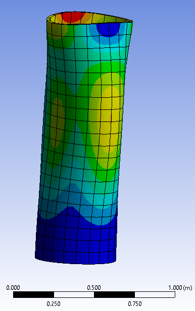
SubscriberI want to apply fixed-fixed support at both ends of cylindrical shell for buckling analysis. Compression load was added and the rotation was fixed at the top surface. I supposed to keep the top surface flat but the result wasn't what I expected. I wonder how to make the top surface fixed in buckling? Could I add a rigid surface at the top and how?
December 7, 2021 at 7:35 amErKo
Ansys EmployeeHi
Just apply a remote displacement on the the top and bottom faces which has behaviour rigid.
(So 2 remote displacements in total, one for the top face and one for the bottom)
Where you apply the force push down (say with 1 mm) with the degree of freedom in the direction of the applied force, and fix the other 5. On the fixed opposite end fix all 6 dof.
Look at the reaction which has the 1 mm down displacement in order to get the buckling force.
The buckling force is just the reaction from the static analysis times the eigenvalue obtained by the buckling solver. So say the reaction is 100 N and the eigenvalue for the first buckling mode is 2 then the buckling load is 2*100 N.
All the best
Erik
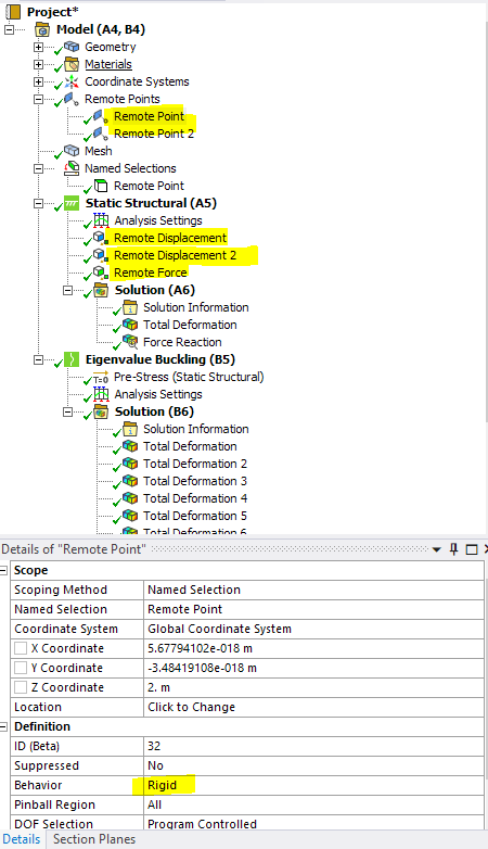
PS: If one wants a force instead of a down movement in the static, then create 2 remote points on these 2 faces (top and bottom), apply remote displacement to one (remote point) leaving the dof free (fix the other 5) in the direction of the force and then apply a remote force to that remote point. On the other side (fixed) just use a remote displacement with all dof fixed. See below for this approach:
December 7, 2021 at 10:49 pmSubscriber
Thanks for the response, it's pretty helpful! I still have several questions and hope you can answer them:
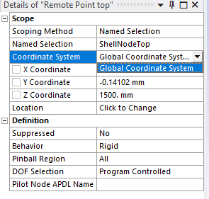
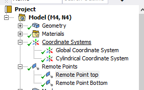
How can I use different coordinate system when defining the remote points? I created a cylindrical coordinate system but can't select it.
 2.I want to see the Poisson's effect on the top and bottom surface, so I just want to fix the displacement in longitudinal direction and let the displacement in other directions free. But it seems like all the degree of freedom would be fixed if I set the surface rigid. Is there any other way to make it?
Thanks Guodong
December 8, 2021 at 7:44 amAnsys EmployeeHi
This is just the location of the remote point and it is always based of course on the global system - for a circular edge / face you just pick them and it will find the centre of that circle to place the point. We can always modify the coordinates (X,Y,Z) manually also by typing in a new value.
We have either rigid, deformable, beam and coupled options - see the help manual for more info if you want byut the names are selexpalnoty in a way.
Also see the help manual ad search for remote displacements and remote points to see what they actually do.
All the best
Erik
Viewing 3 reply threads- The topic ‘How to fix boundary in Buckling Analysis’ is closed to new replies.
Innovation Space Trending discussions
 Top Contributors
-
peteroznewman
 5169
5169 -
scabo
 1836
1836 -
Dennis Chen
 1387
1387 -
javat33489
 1249
1249 -
Shyam Prasad V Atri
1021
Top Rated Tags
© 2026 Copyright ANSYS, Inc. All rights reserved.
Ansys does not support the usage of unauthorized Ansys software. Please visit www.ansys.com to obtain an official distribution.
-


The Ansys Learning Forum is a public forum. You are prohibited from providing (i) information that is confidential to You, your employer, or any third party, (ii) Personal Data or individually identifiable health information, (iii) any information that is U.S. Government Classified, Controlled Unclassified Information, International Traffic in Arms Regulators (ITAR) or Export Administration Regulators (EAR) controlled or otherwise have been determined by the United States Government or by a foreign government to require protection against unauthorized disclosure for reasons of national security, or (iv) topics or information restricted by the People's Republic of China data protection and privacy laws.
