General Mechanical

General Mechanical

Topics related to Mechanical Enterprise, Motion, Additive Print and more.

How to extract running loads and moments from SHELL181 elements in workbench?

    • lolboomepic
      Subscriber

      I'm doing a simple validation study of CLT (classical laminate theory). I made a spreadsheet tool and am confirming to see if FEM gives the same results for stresses and strains. I have a simple model of 4 elements and I'm having a hard time figuring out how to get the running load and moments output from Ansys for each element. In FEMAP/NASTRAN it is very easy to output running loads,moments and stresses but Ansys seems a bit convoluted. I first tried placing a remote point and extracting the reaction forces at that point, but all showed 0 so that was not very useful. Then I tried making an APDL script and that led to a whole host of confusion. The number of elements is way more than what I have in the model (I have 8 elements in my model, but the text file reports loads for 12 elements somehow???). Then I extracted stresses and regular forces and all of those happen to be the exact same. So something is pretty strange/fishy here and I haven't been able to find much help searching online for this so either I'm doing something wrong or there's some way that I'm unaware of. I'd appreciate the help and while I can just do this in FEMAP, I want to learn how to do it in Ansys. 

    • peteroznewman
      Subscriber

      I also use FEMAP/NASTRAN to analyze composite laminate plates and like how easy it is to define the layup and build the model.

      I have very little experience with composite laminate plates in Ansys. I tried it once a few years ago to see the workflow. I decided to refresh that experiece with the latest software. I found a video that shows how to use ACP (Pre) to define the stackup.  The next video shows that and how to use ACP (Post) which includes the stresses in each layer.  Hope this helps.  I'm not sure what you mean by running loads and moments.  Maybe someone else will reply to your discussion.

      While I was following the second video, Ansys 2024 R2 popped up this informational message:

      Following that advice, I inserted a Composite Failure Tool.

      • lolboomepic
        Subscriber

        When talking about running loads, I'm referencing to finding the membrane loads and moments (Nx,Ny,Nxy,Mx,My,Mxy) for an element. In NASTRAN, you just list them as results for each element, so it is definitely possible. Just not sure which knobs to turn in Ansys to achieve that. 

    • peteroznewman
      Subscriber

      Nastran writes no output unless you specifically request it.  Ansys writes most of the output you generally want and you have to change the output request defaults to reduce the output if the result file gets too large.  One item not output by default are Nodal Forces, which you need for what you want.  Under Analysis Settings, Output Controls, set Nodal Forces to Yes and Solve.

      Create a Coordinate System where the XY plane cuts through the model where you want to obtain nodal forces and moments. Right click on that Csys and Create Construction Surface. Drag and drop that Surface onto the Solution branch. A Force Reaction probe will be created for that surface. Select the body that was meshed.

      Click on the Solution branch. In the ribbon, choose the Solution tab and see there is a Probe button, select Moment Reaction. The location is Surface and the Geometry is the body again. Moment reaction has additional settings for Orientation which is best set to the Coordinate System defined for the surface and Summation which is best set to the Orientation System rather than the default of Centroid of the body.

      The Force and Moment Reactions at a construction surface is like the FreeBody tool in Femap. It sums all the forces and moments at nodes on one side of the surface.

      • lolboomepic
        Subscriber

        Interesting. Yea I'm aware of that tool in FEMAP, seems like as you mentioned it's the same with more steps. I feel like there should be a more convenient way of extracting those loads in each element however. Especially if say you want to get data from all elements individually instead of the sum of all the elements like what would output in your suggestion assuming it behaves as the FBD post processing tool in FEMAP. This post for example shows you can output M12 (Mxy) in Ansys but not much instruction on how that is done. Which is more or less what I was trying to achieve with that APDL script I wrote mentioned in the OP. So I feel like there has to be something there that I'm doing incorrectly, but the covenient solution is in that realm. 


    • peteroznewman
      Subscriber

      I struggle to get the FreeBody tool to work in FEMAP and it seems to have about as many steps as the Ansys process.  As a point of reference, I made a little 4 linear element model with a bending force on one side.  

      Here is the Moment Result using the method I described above.  You can see that it is 5 in-lb about the local Y axis.

      Thanks for the link to that post. I can now give you the steps for plotting the Element Moments you want.


      1. Right click on Geometry and Insert Element Orientation, pick the body and define by the Global Coordinate System.
      2. Right click on Analysis Settings, Output Controls, and set General Miscellaneous to Yes.
      3. Solve (you might have to right click on Solution and Clear Generated Data first).
      4. Right click on Solution and Insert a User Defined Result and type SMISC1 to get the Force11.
      5. Right click on that User Defined Result and Duplicate Without Results, edit the Expression to SMISC2
      6. Repeat four more times to get up to SMISC6.


      Here it is with smaller elements.

      • lolboomepic
        Subscriber

        Thank you, that helps a ton! One thing I'm confused about is the units and making sure I know what this is outputting. I've researched a bit and see that SMISC is usually for stresses? With no units, I'm not sure if this is load, load/length or stress. I doubt it's stress by looking at the stress contours and these values not being close, but I'm not sure if this is lb or lb/in? 

        • peteroznewman
          Subscriber

          Since I was in the Units of inches and lbf when I created the User Defined Result, that information was captured and can be seen in the Details window.

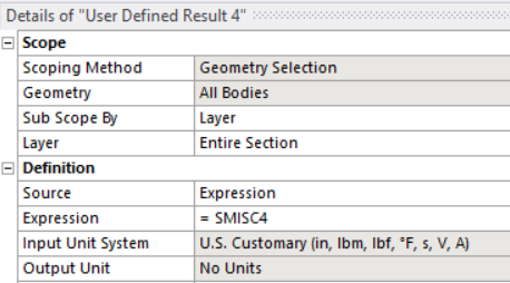
          That means that if I change Units and solve in mm and N, SMISC values will change but the Details window becomes misleading.

          Most output such as moment reaction probes, stress and deformation will respond to changes in Units by updating the output values approprately. For those outputs, it doesn’t matter what Units you solve in. That is not true for SMISC. The values do not update when you change Units. The SMISC values depend on what the Units were when you Solved. The best practice to avoid solving in different units than the User Defined Result details window shows is under Ansys Settings, Analysis Data Management, Solver Units, set that to Manual so you can select a specific unit system such as Bin for the Solver to use, independent of what the Units are set to in Mechanical for viewing results when you hit the Solve button. Then the SMISC output will alway be in the British inch (Bin) units.

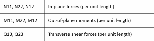
           In Ansys Help, Mechanical APDL, Element Reference, SHELL181 has Table 181.1 that says what the names mean.

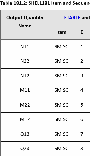
          Then Table 181.2 says what the SMISC number is to get that output.

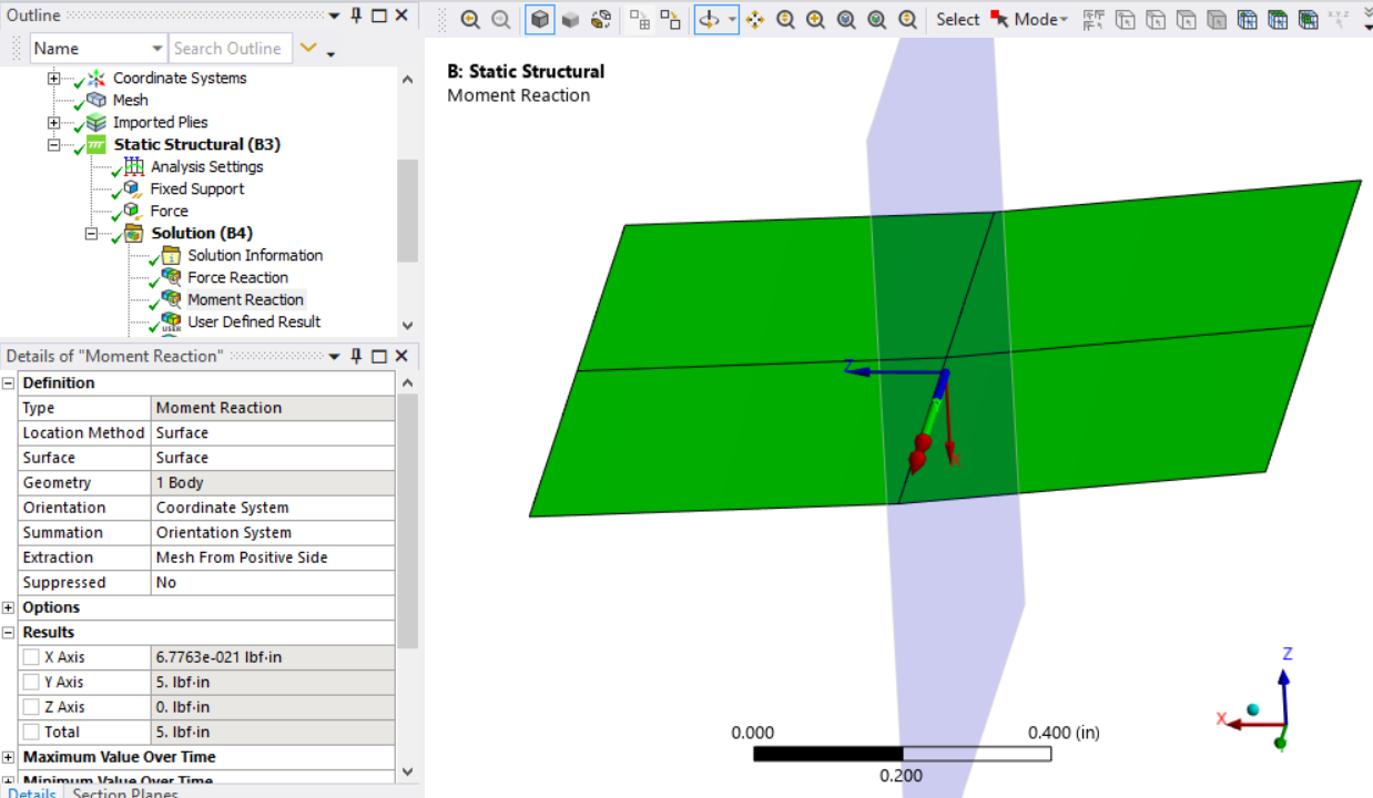
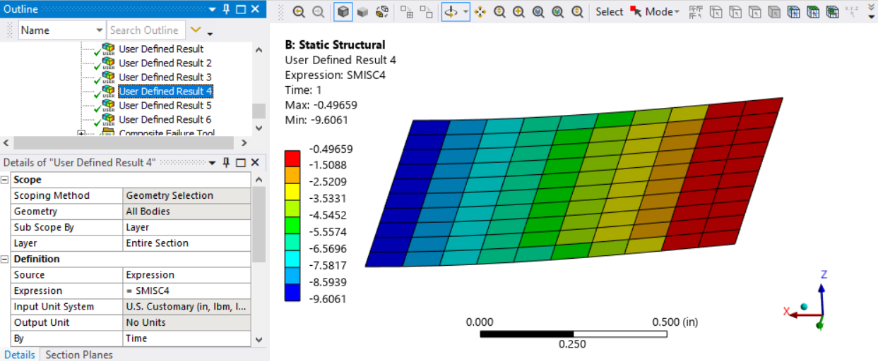
          The average moment is zero on the left (-x) edge where the transverse force is applied and is 10 in-lbf on the right (+x) edge. Half way along the length the average moment is 5 in-lbf.  You can see the SMISC4 output for elements are -4.5 in-lbf/in on one side of the center and -5.5 in-lbf/in on the other side of the center. [edited to add units which are per unit length, the model is 1 inch wide]

          One confusing item is that SMISC4 is for M11, or moments about the X axis, but the large moment is about Global Y. It seems ACP(Pre) messes up the Element Orientation item that was imposed on the shell elements in Static Structural and Ansys warned me about that.

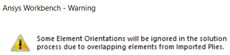
          I don’t work with ACP(Pre) so I’m not sure how to resolve the confusion. Element Orientation worked correctly in other shell models I have done.

        • lolboomepic
          Subscriber

          I understand the units and yes I'm consistently using english units. It's more whether the units are lb or lb/in for forces and for moments I want lb*in/in and not lb*in. Membrane forces and moments is what I'm trying to get, not regular loads. In FEMAP it would be extracted as Membrane X Force, Membrane Y Force, Membrane XY Force, etc.. 

        • peteroznewman
          Subscriber

          Table 181.1 clearly states that the units for In-plane (membrane) forces are per unit length, so in English, it would be lbf/in for SMISC1, 2, 3 and out-of-plane moments are per unit length, so that would be in-lbf/in for SMISC4, 5, 6.

        • lolboomepic
          Subscriber

          Understood. Just found it odd that taking elements from this and plugging into a CLT tool does not provide the same stresses as the contour shows for the certain element. Compared to FEMAP which provides the exact same stress with CLT as FEM for an element on a certain ply. 

    • peteroznewman
      Subscriber

      Do you have a link to the CLT tool that you can share?

      The User Defined Result for SMISC4 with the smaller elements shows in the Details window that the output is for the entire section and not for a ply. Could that be the reason for the discrepancy?

      I am interested to study this further. Please prepare a zip file that has (1) a FEMAP neutral file for Version 12 of your simple test model, (2) an ANSYS archive of the same simple model and (3) any documentation you made that shows the CLT tool result, the FEMAP result and the ANSYS result. I would be grateful if you could reply with a link to that zip file.  Thanks in advance.

      If you are unfamiliar with the ANSYS archive, it is a single file with a .wbpz file extension that combines the .wbpj file with the projectname_files folder where all the other project files are kept.  To keep the ANSYS archive small, do not include results when creating the file.  To create the .wbpz file, in Workbench, use File, Archive.  If the model has a large mesh, you can delete the mesh before making the archive to make it even smaller, but in this case, that is not necessary.

      • lolboomepic
        Subscriber

        Here's a link to the zip with the tool, extracted loads from Ansys for elements and stresses as well as the NASTRAN bdf generated in FEMAP. The main differentiator is the M11 term from Ansys. If I set that to 0, then the resutls come fairly close if I say pluck element 1 running loads from the SMISC data. FEMAP is spot on with the tool and outputs [1,0,0,0,0,0] for membrane loads [Nx,Ny,Nxy,Mx,My,Mxy]. 

        • peteroznewman
          Subscriber

          Thanks for the link. I am away this weekend, so I will look at this next week. I can’t promise any quick answers because I have to do research and study to learn more and digest the CLT tool calculation spreadsheet.

          I looked up a few free courses on laminate theory that are on this site. I have not watched them but might do so as part of my research. Ansys Learning links to laminate theory lectures on this site and CLT beginning at Lecture 17.

        • lolboomepic
          Subscriber

          No problem. I think I provided some decent explantion in the tool and nomenclature. This is also a nice quick summary of the math behind it.

        • lolboomepic
          Subscriber

          Did you get a chance to look at those files? Still in limbo a bit on trying to figure it out in Ansys. 

    • peteroznewman
      Subscriber

      I did look at the files and see that this is a complex issue to analyze. I have an interest in composite materials, but I am not an expert. I mostly use FEA software to solve problems, but sometimes will do a hand calculation to show that the FEM result matches the theory. It’s good that you want to match Ansys output to the CLT result, but this level of study is not something I am willing to dive into at this time. If you figure out how to match Ansys to the CLT, please post a reply. To be clear, I don’t work for Ansys and participate here as a hobby.  Ansys employees responding to questions posted here are not allowed to download any files, but they will point you to Ansys documentation or internet resources. I searched the Ansys documentation and found a Verification Model that uses composites.

      Best of luck!

    • peteroznewman
      Subscriber

      Ansys also supports creating layered sections without using ACP (Pre). This video shows how to do it.

Viewing 6 reply threads
  • You must be logged in to reply to this topic.