-
-
December 6, 2023 at 2:05 pm
Dennis Niklas
SubscriberHi there,
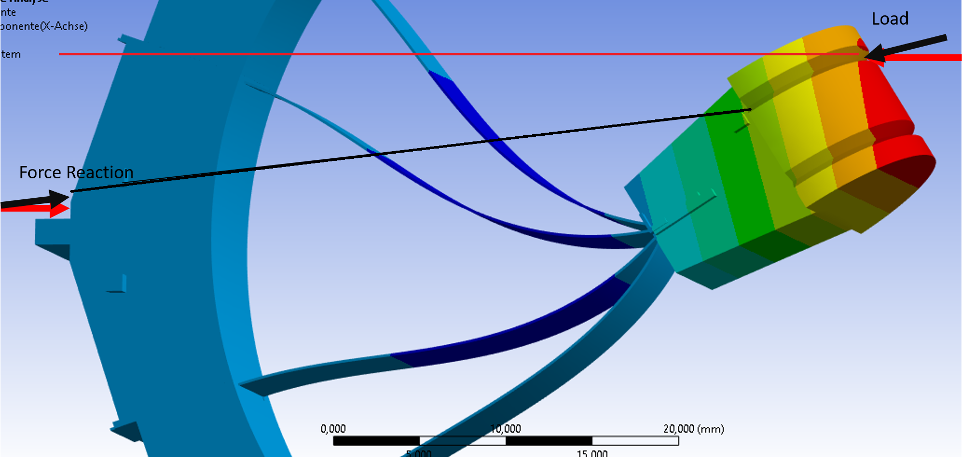
i have a model of a part that has a strong elastic deformation. During the load (a force) the part deforms and the load should change direction, or, in other words, the tip of the force vector should stay at a specific location. You could imagine standing on the left side of the part and pulling on a rope which is fixed on the right side of the part. I have a picture which shows the deformed part with the current force (red, right side) and the current force reaction (red, left side) and the desired force (black, right side) and force reaction (black, left side).
This is a static-mechanic analysis.
-
December 6, 2023 at 2:23 pm
Armin
Ansys EmployeeHi Dennis,
You indicated that the location of load application is at a specific point. How is the evolving direction of the load specified? Is it normal to a particular surface? If so, you can apply pressure instead of force and it always remains normal to the force no matter how the structure is deformed.
As a side note, remember to turn on "Large Deflection" under Analysis Settings to account for nonlinearities arising from large deflection.
-
December 6, 2023 at 2:41 pm
Dennis Niklas
SubscriberHi Armin,
thats correct, the load is a force and its origin is at two specified surfaces. The direction or "target" of the load is the upper square that you can see on the left hand side of the picture (its under the black line and hard to see) and therefore the direction of the load doesn't change currently (which is not what i want). Using a pressure and ensuring its normal to the surface would be a better approximation but sadly is still not my desired load case, especially for large deflections.
Large deflection is turned on.
-
December 9, 2023 at 12:26 pm
peteroznewman
SubscriberDennis, I agree with Armin that a Pressure load is a simple way to implement this. If you create a flat spot in the geometry with a known area, it is simple to convert the Force to an equivalent Pressure.
If you want to use a Force, then you have to implement the Follower Force method. Here is a discussion on making that work with Beam elements.
Good luck!
Peter
-
December 20, 2023 at 9:27 pm
Dennis Niklas
SubscriberHi Peter,
thanks for your suggestions, in the meantime i came up with another solution. I wrote an APDL Code which works mostly i guess.
Here is the Code:
I used the “sourceCode” Button hopefully it doesn’t mess up the formatting.
I created two components, one for the source (a area full of nodes, 37 to be specific) and one for the target (which i’ve hard coded). Now, instead of computing 30 substeps i compute 30 individual timesteps. In each of them the force is increased by 1/30 and the deflection of the source and the target is evaluated. I then compute the distance between the area (source) and the point (target) and compute the directions in x,y,z. The force is then applied to each node equally.
It does work, i can see the force reaction to change direction. But somehow it the force points downward a little which does not make any sense because the points are on the same level. I compute the distance between the area and the target-point by computing the middlepoint of the area first, i guess the nodes aren’t equally distributed, therefore the computed midpoint isn’t the real midpoint i guess.
My next problem is, that i write some data into a kinda debugging file and it seems like that my coordinate system which i created in Workbench is not respected. In Workbench i can see the “CoordSys1” and the force reaction is displayed in said coordinate system but the data in the debug file has x and y flipped and z is -z.
Maybe somebody has an idea, it seems that there isn’t much data available online on how to write good APDL Code. At least i couldn’t find any…
Thanks,
Dennis
Edit: of course it did mess up the formatting of the Code....
Here is the Code with hopefully better formatting... https://pastebin.com/6NrV1ZWc
-
- The topic ‘How to ensure that Tip of Force Vector stays at specific location?’ is closed to new replies.


-
5094
-
1830
-
1387
-
1248
-
1021

© 2026 Copyright ANSYS, Inc. All rights reserved.


