TAGGED: acp-pre, aerostructural, contacts, shell-elements, static-structural
-
-
June 16, 2021 at 7:35 am
pedrob
SubscriberHello all,
I am trying to model a wing that has the main spar separated and it's connected only by those two ribs and tubes. When in flight, there is a locking mechanism (not represented) that bonds both wing together.
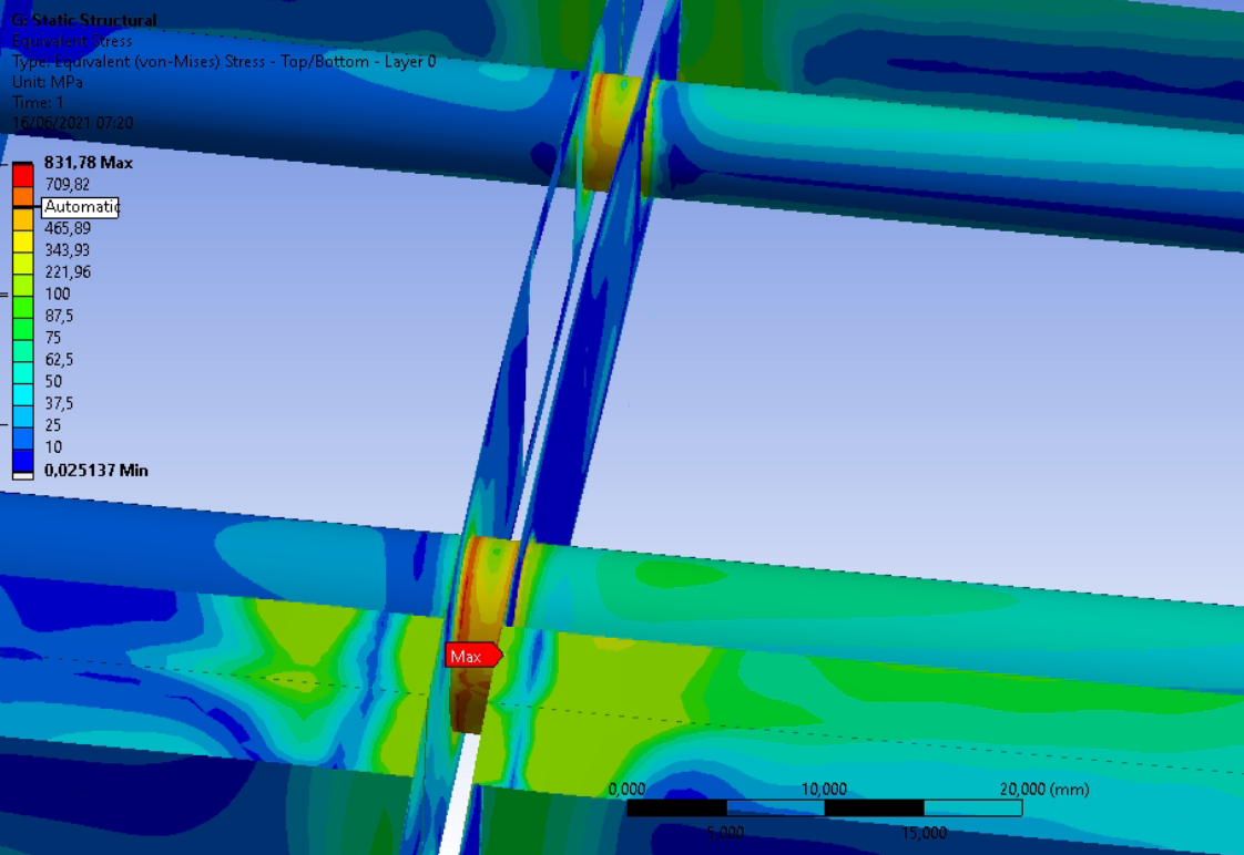
I have been working on this model for while and this is the only part that I havent been able to solve. There is no analytical answer for this part. I have created a bonded contact between the two sperate surfaces and then I used and edge to face connection, to connect the ribs to the tubes. However, in the simulation, when I run it, I find this problem. I cannot understand if this and accurate representation, since, indeed this tube will have to handle with the cantilever loads of the outer wing or if it a stress concentration. I am using large deformations since it's a large wing. I am also using ACP to accurate model my composite materials.
June 17, 2021 at 6:38 am1shan
Ansys Employee"....there is a locking mechanism (not represented) that bonds both wing together" - The contact should most accurately represent the force transfer via the locking mechanism. Since the locking mechanism is not known its hard to tell what might be the most accurate way to define the contact. If the ribs are fixed on the pipe at the holes then you may define a bonded contact between the edges of these holes and the pipe surface. The contact and target side which you defined do not look very realistic to me, since they are in no way connected to each other right? I also see 2 more holes (one front, one back) on the ribs. If there is a stud running through these holes you can connect them with a revolute joint (if they are allowed to rotate) or a fixed joint/bonded contact (if they are not allowed to rotate). Also, there is no need for a mesh connection if you are using a bonded contact. Using a mesh connection distorts mesh elements in many cases. You can see this happening in the last image, near the rib pipe intersection.
Regards Ishan.
June 17, 2021 at 8:15 amSubscriber
Thank you so much for your response. I hope you find yourself well. Thank you for the explanation between mesh connection and using bonded contacts, I was not aware!
The locking mechanism, is a just a simple hinge (not modelled) that guarantees the continuity of the wing. I did not modelled it because I wanted to have a global model of the wing. I was thinking of doing a local model wing the hinge in mind and use shared topology and results from this simulation. Do you think that, I should add it to this model? It would increase contact complexity and I just want to have a overall idea of wing displacement and stresses. I have been having very good results overall, the only problem in this part of the simulation.
However, indeed the two ribs are not connected. It's the hinge that hold them together and the tubes are use to transfer the load from one outer part of the wing to the center. As such, when in flight, it is hoped that they do act one piece, as they were bonded. Thus, I used a bonded contact between the two surfaces.
Sorry I did not understood very well, the problem with the contact targets. You recommend me to use a bonded contact between the rib holes (the ones that have a tube passing by) and the tube, is that it? (they are not allowed to rotate).
"...The contact and target side which you defined do not look very realistic to me, since they are in no way connected to each other right?", Was this for the contact between the tube and the rib or the contact between the ribs? The other holes that your see they do not have major structural components (it's for cables and weight saving).
Thank you for your times PBrandao
June 17, 2021 at 12:20 pmpeteroznewman
SubscriberWhat does the hinge look like? A door hinge has two rectangular plates connected by a pin.
A simple way to model the hinge in a system model is to imprint on the rib the two areas where the hinge plates fasten to the rib. Add a Revolute Joint scoped to those two areas and align the revolute axis in the correct direction and in the correct location. You have to choose how the scoped areas of the Joint behave: Rigid or Flexible. If the Hinge Plate adds significant stiffness to the rib, then Rigid might be a good choice. If it adds little stiffness, then Flexible would be a good choice.
Opposite the hinge is the locking mechanism, which again will have some limited area on the rib where the locking mechanism is fastened to one rib and clamps on the other rib. Add a Joint type = General scoped to these two areas. A coordinate system was created under this joint. Let's say that the X axis of this coordinate system is normal to the rib surface. The primary function of the lock is to prevent motion of the two clamped surfaces from moving relative to each other in the X direction. At a minimum, you would include the X direction as active in this Joint. But maybe the locking feature also prevents motion in the Y or Z directions, so you can add those DOF to the Joint definition. The same choice of Rigid vs Flexible must be made on this Joint.
Bonding the entire rib surface seems like it would create a much stiffer connection than the hinge and lock actually deliver.
June 17, 2021 at 2:48 pmSubscriberHello peter!
Thank you so much for your clear answer. Indeed, bonding the two surfaces can create a very stiff connection, as we observed above. However, should I still apply a contact between the two surfaces, maybe frictionless or no separation contact to avoid penetration?
The hinge is similar to a door hinge, however in a different lay-out. We have one of the hinge plates (Area 1) fasten to a component (in red), that will be bonded (glued) to the respective ribs. Then the locking plate, in a similar manner will also be fasten to a component (in red) that will be glued to the ribs.
 As such, similar to what you have suggested, I could create a surface with two areas and give the revolute joints between them and a fixed joint between the areas and the respective ribs. In a similar manner the wing skin is also separated, but I have modelled it only as one surface. Should I also separate them to avoid a "way" too stiff connection?
Since the thickness of the plate is small, I think I will use flexible joint. Thank for your clarification.
Thank you so much for your time.
June 17, 2021 at 8:02 pmSubscriberYes, the wing skin should be two surfaces and not cross the hinge line.
I would have no contact between the ribs and rely entirely on the hinge and lock joints. The benefit of that is the model remains linear, making Modal analysis and Harmonic Response analysis possible. Also, you can recover the forces going through the Revolute Joint and apply those forces to a detailed breakout model to see the stress in the hinge components that have to carry the force applied by the hinge pin. In the same way, you can recover the forces going through the General Joint and apply those forces to a detailed breakout model to check the stress in the lock parts.
June 17, 2021 at 8:23 pmSubscriberI think I got it!
Thank you so much for your help. I will let you know later, the conclusion that I have taken from that approach.
Viewing 6 reply threads- The topic ‘How to do a contact between two separate shell faces?’ is closed to new replies.
Innovation Space Trending discussions
 Top Contributors
-
peteroznewman
 5814
5814 -
scabo
 1906
1906 -
Dennis Chen
 1420
1420 -
javat33489
 1305
1305 -
Shyam Prasad V Atri
1021
Top Rated Tags
© 2026 Copyright ANSYS, Inc. All rights reserved.
Ansys does not support the usage of unauthorized Ansys software. Please visit www.ansys.com to obtain an official distribution.
-