-
-
August 5, 2024 at 5:03 pm
1617836513
SubscriberI'm doing a torsional performance test on a screw, and I want to limit the deformation of the drive body and apply a remote displacement to the outside of it, and finally use the remote displacement as a boundary condition to output a counter moment. Setting the body as a rigid body will conflict with the boundary condition of remote displacement. How should I set it up to realize the "using plane elements to define the rigid surface of the screwdriver" in the orange part of Fig. 2?ÂÂ -
August 6, 2024 at 1:27 pm
Ashish Khemka
Forum ModeratorHello,
Please see if the following thread helps: Defining rigid body and contact (ansys.com)
Regards,
Ashish Khemka
-
August 7, 2024 at 6:23 am
1617836513
SubscriberÂ
Hi, I know how to set the part as a rigid body. But after I set the drive part as rigid body, I have the following problem:
  The drive part is not fully meshed, why is that?
  I want to add a distal displacement to the surface of the drive part that rotates around the Z axis, which will conflict with the constraints of the rigid body.I want to achieve something like figure 3 and 4.
-
August 7, 2024 at 3:57 pm
-
-
August 7, 2024 at 10:11 am
Ashish Khemka
Forum ModeratorHi,
Is the driver part a rigid body? Genereally mesh is generated for surfaces on rigid body which are in contact. Turn off the weak spring. You can specify rotation on the rigid body via remote displacment.
Regards,
Ashish Khemka
Â
-
August 7, 2024 at 4:19 pm
-
-
August 8, 2024 at 5:42 am
Ashish Khemka
Forum ModeratorAbove is a warning message, please check if the results look fine even with the above message.
Regards,
Ashish Khemka
-
August 8, 2024 at 8:20 am
1617836513
SubscriberHi, I don't think this answer makes sense, why would the drive part, being a rigid body, also deform?
-
-
August 8, 2024 at 9:23 am
Ashish Khemka
Forum ModeratorÂ
Hi, I was not talking about the deformation but about the warning message. The deformation results you shared is that only for rigid body? Please comment.
Regards,
Ashish Khemka
Â
-
August 8, 2024 at 10:20 am
-
-
August 8, 2024 at 9:51 am
-
August 8, 2024 at 11:44 am
1617836513
SubscriberHi,Â
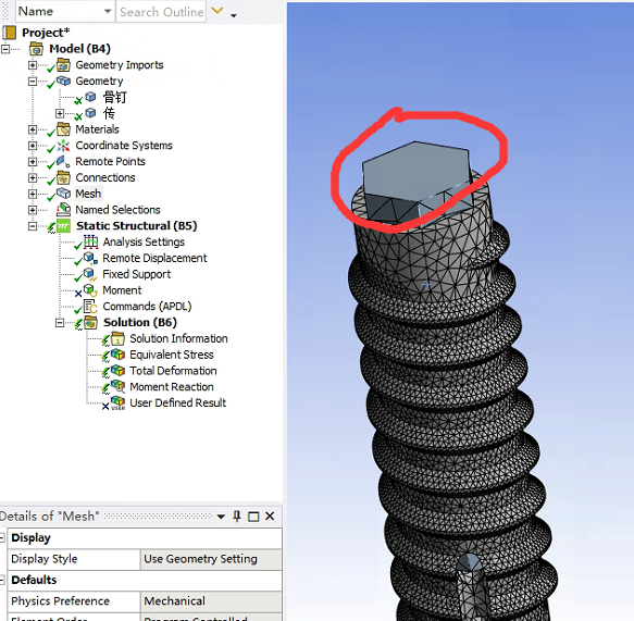
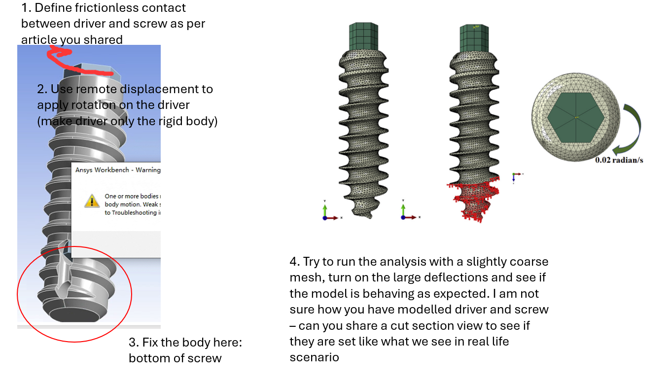
As you said, I set up the driver as a rigid body and created a remote point using its six sides.Â
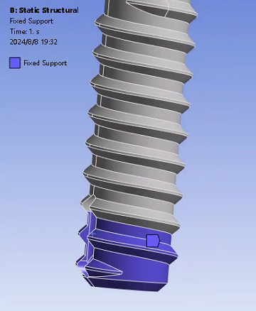
After that, I added a 0.1rad remote displacement of the Z-axis at the distal point, as shown in figure one. The bottom of the screw was fixed as shown in Fig. 2 and set frictionless.
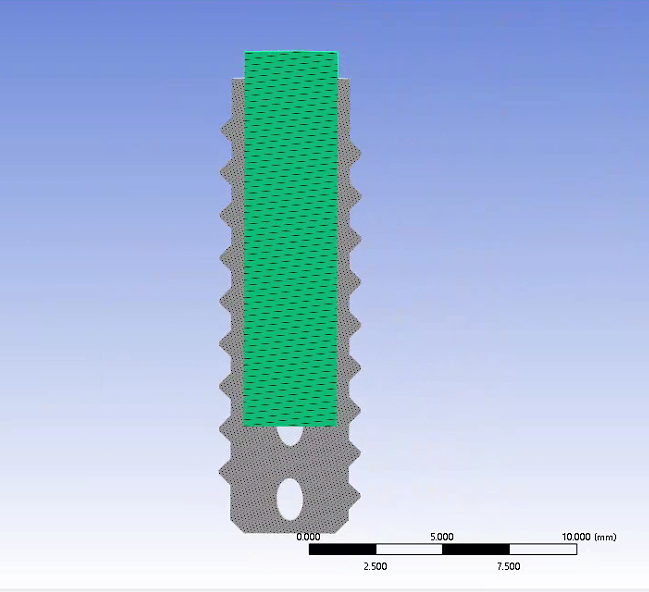
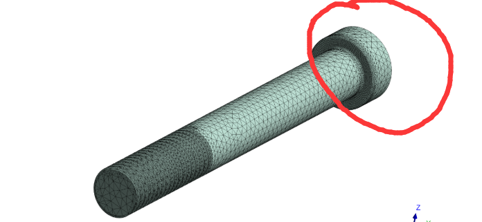
The profile of the geometry is shown in Fig. 3.
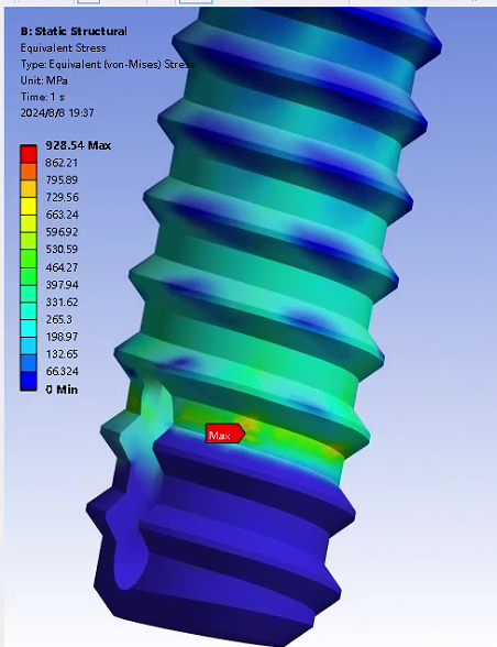
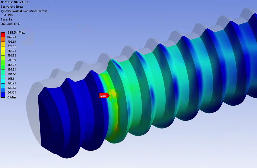
Figure 4 shows the equivalent mises stress of the screw.
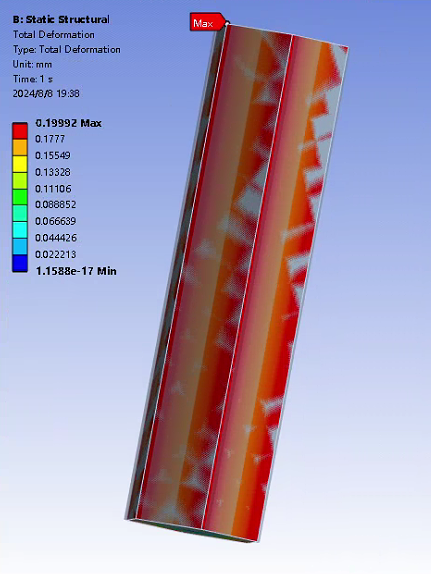
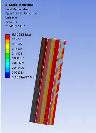
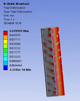
Figure 5 is a diagram of the total deformation of the drive section.Figure 6 shows the value of the counter moment at the remote point. 
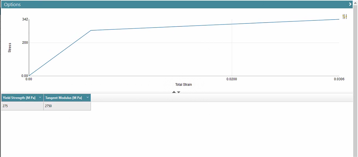
The same material properties are used for the transmission part and the screw as shown in Fig. 7, E is 45 GPa, v is 0.3.Â
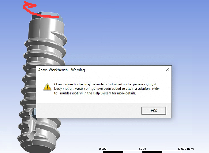
I feel that this result is a little bit not reasonable:The driver, being a rigid body, produces a non-negligible deformation.
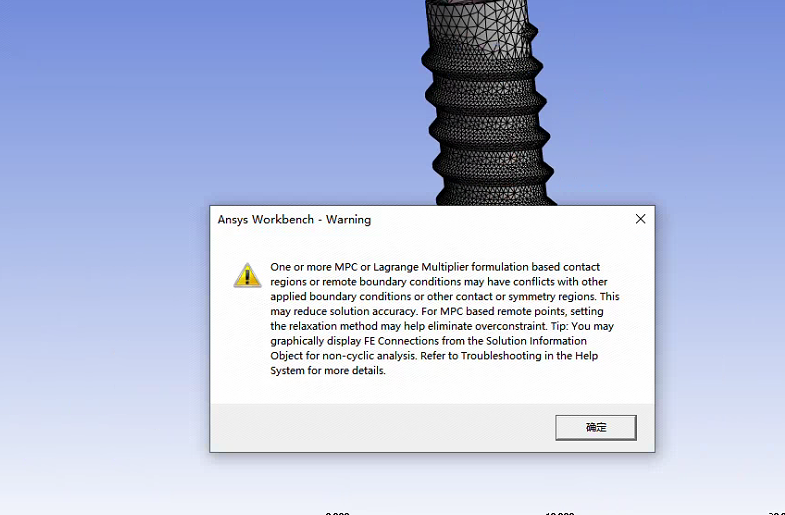
The values of the equivalent force of the screw and the counter moment at the remote displacement seem to be too large. But I don't know where the problem is..Â
Â
-
August 8, 2024 at 11:53 am
-
-
-
August 8, 2024 at 12:44 pm
Ashish Khemka
Forum ModeratorHi,
For the peak support I think the mesh is not converged and may be refining mesh will change the location. Otherwise without having a look at the model it would be difficult to comment. If you have access to support then please raise a case. Ansys employees cannot download the model from forum. Meanwhile please wiat for other members to comment.
Regards,
Ashish Khemka
-
August 8, 2024 at 1:16 pm
1617836513
SubscriberCan you tell me how to raise a case? thanks.
-
-
- You must be logged in to reply to this topic.
-
2457
-
931
-
599
-
591
-
586
© 2025 Copyright ANSYS, Inc. All rights reserved.