TAGGED: -waveguide, convergence, eigenmode, mode-expansion, troubleshooting
-
-
October 17, 2023 at 1:23 pm
Duarte Silva
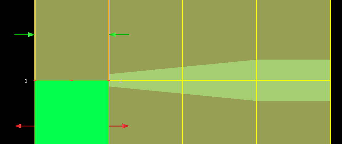
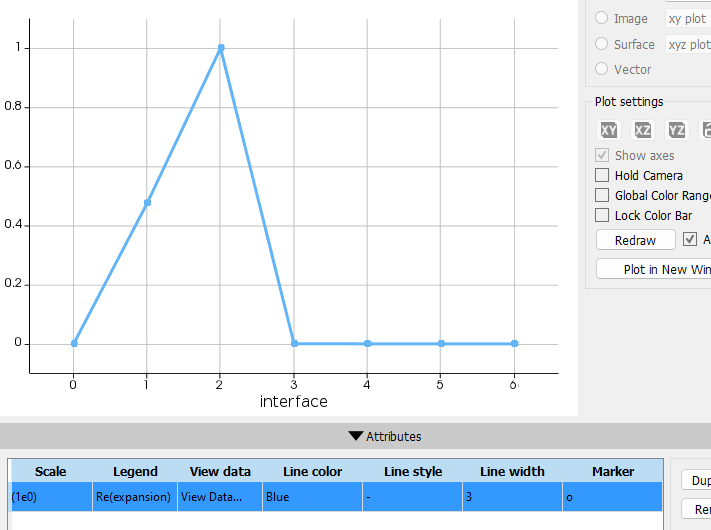
SubscriberI am studying a vertical taper system where light couples from a waveguide from below to a top waveguide. To do so I am using a linear taper on the top waveguide like below. However I kept running into problems with respect to mode convergence: I would end up needing a lot of modes, which didn't make much sense. I started looking into the expansion error and found that there is a huge peak on the transition at the thin end of the taper.
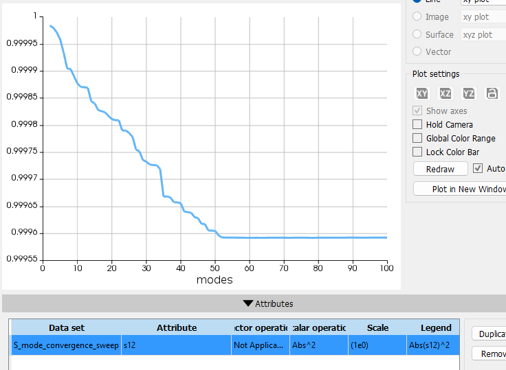
In an atempt to minimize this error I decided to add a new cell group surrounding this abrupt transition and calculate in this reagion 100 modes. Therefore, for this new simplified version I have a first group cell which is just a simple propagation through 10um and then a small group cell of 20nm that encompasses the abrupt transition. Despite achieving mode congergence according to the mode convergence sweep tool, I still get a big error on the mode expansion through the global diagnostics data set. Can anyone comment on the the expansion error? The only information I found was in here (Understanding EME error diagnostics – Ansys Optics) from which I throught I had understood as projecting the mode on the left to the basis on the right and see how well it would be represented on the mode basis on the right. However, the fact that the value I get seems to be independent of how many modes I decide to use has me confused.
-
October 17, 2023 at 6:28 pm
Amrita Pati
Ansys EmployeeHi Duarte,
Thanks for sharing detailed information. Would you also be able to share a screenshot of the structure with the bottom waveguide? I believe the taper that is shown in the first screenshot is the top waveguide? Is it more like an inverse taper structure used in edge couplers? I would like to understand what the overall structure looks like. Also, I believe you are just looking at the coupling between the two waveuguides? Not the overall propagation through the top waveguide after the coupling?
Regards,
Amrita-
October 17, 2023 at 6:38 pm
Duarte Silva
SubscriberHi Amrita,
The bottom waveguide is just a rectangular waveguide with no change along the propagation direction. Below is a very quick representation of it in power point. The light is inserted from the fundamental mode of the purple waveguide where there is no green waveguide. After 10um the taper of the green waveguide starts. That is the abrupt transition.
->Also, I believe you are just looking at the coupling between the two waveuguides?
I’m afraid of there being a miscommunication here but I think so. I want light to enter through the purple wg and couple into the green one. The refractive index of the green one is much higher than the purple one. Hence the tapered transition.
->Not the overall propagation through the top waveguide after the coupling?
The full system does have a section at the end of the taper and I am analysing the propagation along the x direction.
In case it helps you understand better where my question comes from: I'm trying to avoid having to do a mode convergence sweep with a large number of modes. The reason for that is that I expect to be needed a large number of modes on abrupt transitions but a much smaller number on smoothly varying regions, so there is no need to set all the sections with the same high number of modes. This would save on computational time.
-
-
October 17, 2023 at 7:02 pm
Amrita Pati
Ansys EmployeeHi Duarte,
Thanks for explaning, that makes things much clearer. So, if I were to look at the two waveguides and the EME region from the top (x-y view), would it look something like this?
At this point I am thinking that one of the possible causes of the expansion error could be radiative leakage in the vertical direction. But I would like to make sure that I understand the geometry correctly before I come up with more details.
Regards,
Amrita-
October 17, 2023 at 7:33 pm
Duarte Silva
SubscriberHi Amrita, in that case let me give you some more details on the geometry and materials so that you may be able to replicate:
The purple waveguide is contained in the yellow material, so in your xy view I would expect to see green and yellow, as opposed to green and purple. The yellow material has a refractive index of 1.5 (n=1.5), the purple n=2, the green has n=3.35. The width of the purple wg is 1600nm and 300nm in height. The green has a tip width of 100nm and a height of 350nm. The spacing in the z direction between the purple and green (filled with yellow material) is 100nm.
As for the simulation region, I believe that would be enough to replicate the results. Though my attempt involved two group cells. The first ended 10nm before the green tip and the second had a length of 20nm.
I was using metal boundary conditions throughout.
-
-
October 17, 2023 at 7:50 pm
Amrita Pati
Ansys EmployeeHi Duarte,
Thanks again! Let me look at this in detail and get back to you.
Regards,
Amrita -
October 19, 2023 at 10:03 pm
Amrita Pati
Ansys EmployeeHi Duarte,
Thanks for your patience! I looked at you simulation in more detail, and here are a few things that I would ask you to consider:
- The position of the input port. Make sure that you are injecting the fields into the bottom waveguide and not the free space just before the start of the waveguide. Before you run the simulation, visualize the fields of Port 1. Also make sure that the structure is resolved properly by looking at the index. For ex. if you look at a structure like yours, the index and fields at Port 1 look like this:
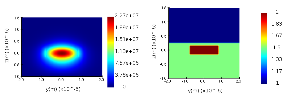
But if you inject the fields right at the edge of the structure (where it starts, which looks like you might be doing in your simulation), it would look something like this (which is incorrect):
In case you are doing this, this could be the reason behind the large expansion error. As these are free space modes that EME is not very good at simulating and might require a large number of modes fir expansion. - The position of the Output Ports. You should position the 2nd set of ports at the end of the taper rather than the start of the taper. What this is doing is not even considering the taper. So, even though there is a large expansion error you don't see any change in the Transmission because it is not even considering the taper structure, so the Transmission is basically 1, no matter how many modes you use for the expansion. So, what you can do is extend the simulation domain in the x-direction. With this you can also characterize the mode interaction happening at the abrupt transition in the geometry as you go from one waveguide to the other.
- In terms of the cells. I would ask you to use one cell for the bottom waveguide, and then a series of cells with CVCS subcell method for the taper. You do not need to have multiple cells at the bottom waveguide side because the cross-section of the waveguide is constant. So, even if there is an abrupt transition, you only need to consider the cross-sections of the waeguide. As long as the cross-section is constant you only need 1 cell. So, in this case the cells should look something like this:
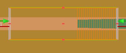
1 cell for the bottom waveguide and multiple cells for the top waveguide as it is a taper.
If you need more insights into the setting up of the simulation, you can refer to the edge coupler example, which is also vertical coupling. Although different from your geometry it can still provide crucial insights: Edge Coupler.
After you make all these changes, if you see unexpected behavior/results, let me know and we can discuss convergence testing and error diagnostics in more detail. I believe you have already looked at the error diagnostic page. But here is another article that can give you an intuitive picture of the convergence testing process in EME: EME Convergence Testing: An Intuitive Approach.
Please let me know if you have any questions.Regards,
Amrita - The position of the input port. Make sure that you are injecting the fields into the bottom waveguide and not the free space just before the start of the waveguide. Before you run the simulation, visualize the fields of Port 1. Also make sure that the structure is resolved properly by looking at the index. For ex. if you look at a structure like yours, the index and fields at Port 1 look like this:
-
- The topic ‘How to deal with abrupt transitions in EME to reduce expansion error?’ is closed to new replies.


-
4613
-
1530
-
1386
-
1209
-
1021

© 2025 Copyright ANSYS, Inc. All rights reserved.

