-
-
July 15, 2021 at 11:03 am
Dubey92
SubscriberI am modeling Selective Laser Melting(SLM)/Laser Powder Bed Fusion(L-PBF) in Fluent. I have already modeled particles over a flat bed using DEM and have extracted particles radii and coordinates. Is there a way I can create these particles in Fluent?
I am using VOF with Solidification/Melting and have a solid block over which I want to create the particles. I know that I can use cell registers to create a particle and give it a phase fraction corresponding to metal. But it will take a lot of time creating single particles using Cell Registers and patching to metal phase fraction.
Other way is to write a UDF and initialize the Volume Fraction for all the particles using spherical domain. Is there a way I can read the coordinates and radii data from my DEM file and create all the particles in the UDF using DEFINE_INIT?
July 15, 2021 at 1:00 pmRob
Forum ModeratorYou can use a journal to create the spheres to then patch many spheres at once. Note, the sphere will be a little rough as Fluent doesn't include part cells in the registers. You'll also want the smoothing options (bottom left of the patch panel) when you add the "liquid" phase.
July 15, 2021 at 1:28 pmDubey92
SubscriberThank you for your reply sir. I will try what you have suggested. Till then please don't close this query section.
July 23, 2021 at 5:49 amDubey92
SubscriberAs I understand, I need to create a journal file that can read particles' radii and coordinates from my data file and create spherical regions and then patch them with secondary phase volume fraction.
My doubt is that I have assigned two fluid regions, one for the inert gas and the other for the metal. The particles will be above the the metal block. What I see in the Boundary Conditions in the Fluent GUI are Inlet, Outlet, Walls and the interior.
When I want to display the interior fluid region by remove walls in the display port, it shows blank. And all my particles will be inside the fluid region only. So will they be visible after the simulation if I remove the gas domain walls? Please correct me if I am wrong.
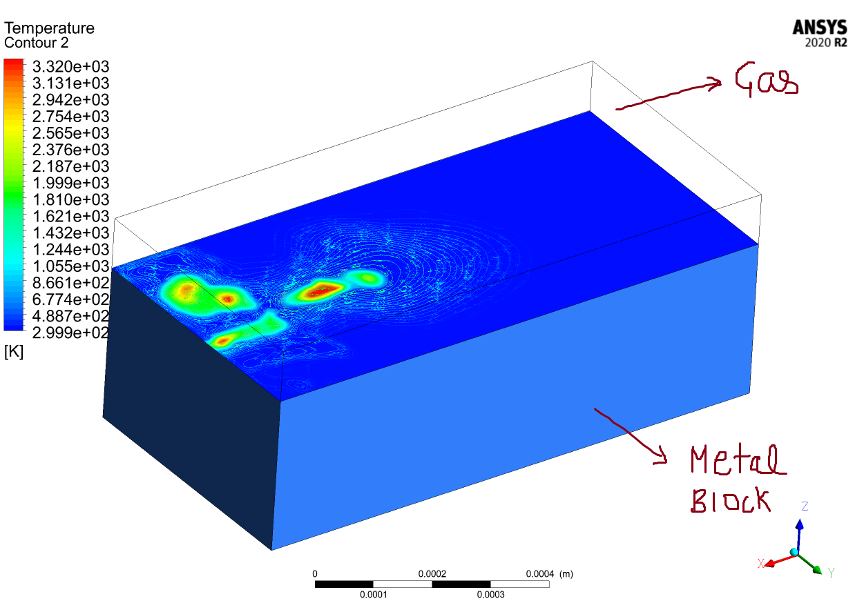
My particles will be above the metal block and the gas will enter at one end and exit at the other end.
July 23, 2021 at 8:47 amRob
Forum ModeratorI'm not sure I quite understand the question.
The adaption registers aren't a separate cell zone, they're marked cells to then patch in the "solid" material that will melt. If the spheres are smaller than the cells you'll not mark anything. To view the marked spheres use the Display option in the Adaption tool, or the solid/liquid fraction on the contours.
July 23, 2021 at 9:06 amDubey92
SubscriberThanks for your reply. My spherical particles are not smaller than the cell size.
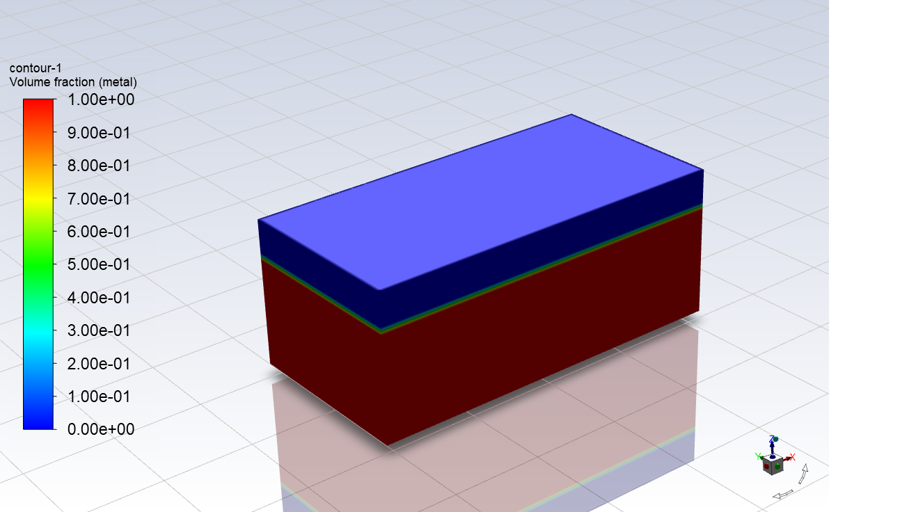
As in this figure, I have used "Cell Registers>New Region>Hexahedral" first to create a region with the metal block dimensions and then used patch to assign it the metal volume fraction.
My question is how to patch the metal volume fraction in a similar manner to a large number of spherical particles(I have the coordinates and radii) above the lower metal block?
As you suggested earlier, should I create a journal file to read the particles coordinate and radii from my data file and then use patch for the same? Is this the way to use a journal file?
July 23, 2021 at 10:36 amRob
Forum ModeratorI'd use a journal to create all of the registers, then manually patch the material into those registers. So you need to add the position data into the journal: Excel is a good tool for this as you can put the commands into cells & then copy the text file position data into that.
July 23, 2021 at 10:41 amDubey92
SubscriberThanks for clarifying. Now I understand the procedure. I will try to implement this. Till then, please don't close this thread.
July 23, 2021 at 8:25 pmDubey92
Subscriber
July 30, 2021 at 6:10 amDubey92
Subscriber
July 31, 2021 at 8:14 amDubey92
SubscriberHello Sir, I created a journal file to create the spherical particles. I have a large number of particles over the solid block(around 1300). I used the following command to create a spherical cell register:
mesh/adapt/cell-registers/add particle1 type sphere inside yes center -0.000418656 -0.000143554 0.0000125 radius 0.0000125 q q
And then I repeated this command for all the particles with changed name. But I get a error: Maximum number of cell registers allowed is 31.
Can you please tell how to overcome this?
August 2, 2021 at 2:46 pmRob
Forum ModeratorYou'll need to create the particles and patch in sequence. There must be a hard coded limit to the number of registers that can be created to avoid creating files with excessive amounts of data. How many particles to you need?
August 2, 2021 at 3:30 pmDubey92
SubscriberSir, currently I have around 1300 particles with a uniform diameter of 25 microns. Even if I increase the size, the number of particles will not be less than 500-600. But I know that more number of particles can be patched as I have seen published results of same simulation done in FLUENT.
Should I create the particles in a batch of 31(the limit shown during adaption) and then patch these 31 particles? Will I have to delete these registers every time I have patched to create new particles in cell registers? Please give your suggestion.
August 3, 2021 at 1:23 pmRob
Forum ModeratorYou will, but if you set the journal up to initialise, create 30 regions, patch, clear regions etc it shouldn't take much longer and you can use Excel to build the journal file. Never use the max number of anything if you can avoid it as it leaves no room for errors.
August 3, 2021 at 2:21 pmDubey92
SubscriberThank you for your reply sir. I have created the journal file using excel and working on patching the regions. There is some issue with the visualization of marked spherical particles. In the display option, I don't see the particles. I am looking into it. Till then, please don't close this thread.
August 3, 2021 at 2:50 pmDubey92
SubscriberThis is the issue I was asking about. I created first 30 particles using create cell registers. Then I patched a few of them manually one by one with metal volume fraction. But as shown, I can't see the particles in the display option. Maybe I am doing something wrong. Kindly help.
 I am able to see only dots in place of particle locations.
But there are published results as one shown below which have done this using patching regions only.
 This is a published result. Please give your suggestion.
August 3, 2021 at 3:26 pmRob
Forum ModeratorHow big are your cells relative to the particles? Remember registers will only tag cells that are entirely within the sphere you define.
August 3, 2021 at 3:44 pmDubey92
SubscriberMy cell size is 10 microns and my particle size is 25 microns. On average, 8 cells are marked for each sphere which I can see after patching in TUI.
August 3, 2021 at 3:51 pmDubey92
SubscriberBut the cells are hexahedral and the particles are spherical in shape. Even if a spherical register tags only those cells that are completely inside, I should be able to see a sphere. Can you suggest where I might be wrong?
August 4, 2021 at 8:27 amRob
Forum ModeratorIf your particles are 25 microns your cells want to be 2-4microns to resolve the volume. Otherwise you may as well model cubes.
August 4, 2021 at 8:49 amDubey92
SubscriberThanks for your suggestion. I will try to implement this. I also have a general doubt about the display. I am using solidification/melting and as I understand my domain will be basically a fluid in which FLUENT will add a source term for momentum equation. Now, the walls will be automatically assigned as solid and I can give a zero thickness for walls.
My question is when I try to display the domain without the walls, the fluid domain is empty. It doesn't show anything. I can only see my geometry if I set the walls in display otherwise the interior region looks empty. Is it correct or am I committing some mistake?
August 4, 2021 at 8:53 amAugust 4, 2021 at 10:28 amRob
Forum ModeratorYes, the "solid" that melts isn't a solid it's a fluid that's not moving: read how the model works.
August 4, 2021 at 4:06 pmDubey92
SubscriberThanks for your help, I reduced the cell size to 3 microns and was able to resolve a 25 microns particle as a sphere. Although, it is not completely taking the shape of a sphere. Please suggest how to smoothen the shape of the sphere?
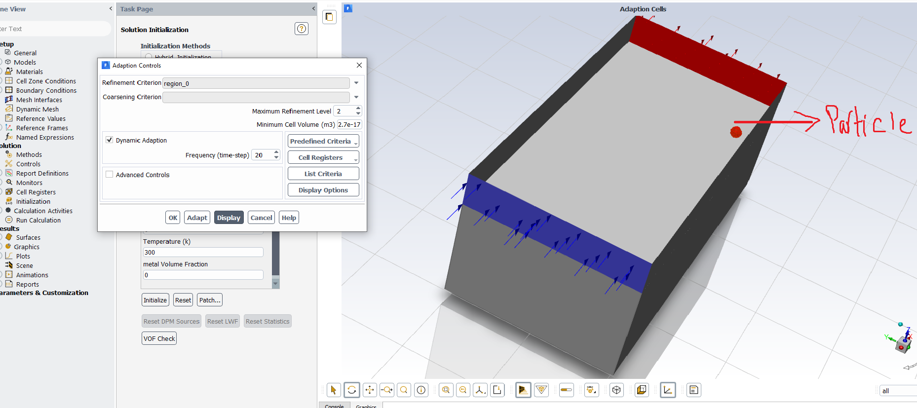
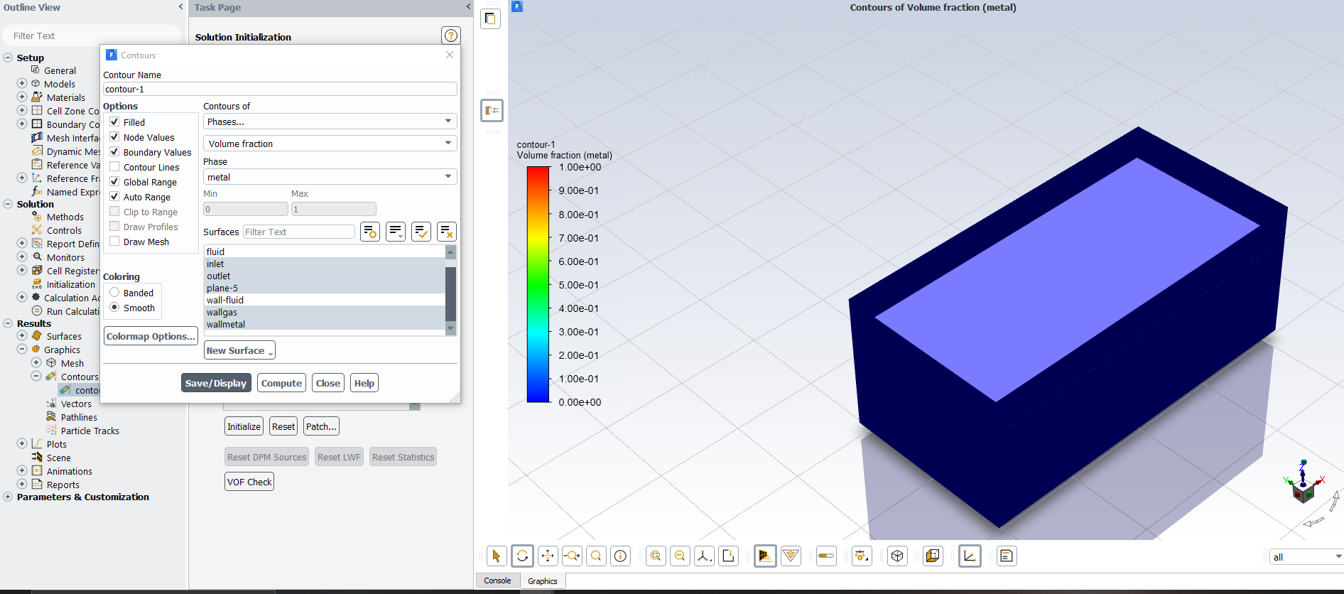
Also, when I patched the particle with a secondary phase after initializing the solution, I plotted the contour of volume fraction of secondary phase but did not see the spherical particle. Is it that FLUENT doesn't show fluid domains as bodies that's why I cannot see the particles? Will I be able to see them after the simulation in CFD-Post? I will be melting these particles using a moving laser? Is there an option to visualize them in CFD-Post?
August 5, 2021 at 12:14 pmRob
Forum ModeratorPlot an isosurface of metal (I assume that's a fluid material) at a volume fraction of 0.5 and see what comes up.
For better capture of the spheres further reduce the cell size: you're trying to capture the spherical shape with hex/tet elements.
August 6, 2021 at 11:59 amDubey92
SubscriberSir, thanks a lot for your help, over the past few days, I have learnt a lot and making progress on a daily basis. I have plotted the iso-surface for the particles. I patched the particles with a metal volume fraction 1.
First image is for iso-value of 0.5. In this the particles look more spherical but the particles surface become joined. I don't understand why this is happening. Moreover, I have given a volume fraction of 1 for the region of particles, so is it accurate to go with this?
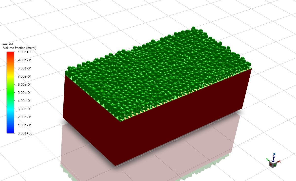
The second image is with iso-value 1. In this, the particles don't exactly look spherical. As for reducing the mesh size, I have already reduced it to 3 microns and due to computational constraints, I don't think I can reduce it any further. Although, I can Increase the particle size.
I want to move a laser over the particles and for that I have give a condition in the source term: 0.05 < C_VOF(c, metal_thread) < 1.
August 6, 2021 at 12:00 pmAugust 6, 2021 at 12:57 pmRob
Forum ModeratorLook at how the VOF model resolves the gradients between the phases. There's the gas phase, liquid phase and the "messy bit" at the interface. With sufficient mesh that latter section may be 1-3 cells across so the choice of VOF value will alter the shape of the surface.
Increasing the sphere size relative to the current mesh will also improve the curvature capture. If you have any, draw a few circles on squared paper as that's pretty much what we're doing with the adaption registers.
August 6, 2021 at 1:54 pmDubey92
SubscriberThanks for your suggestion. Now, I changed the iso value to different values and saw the interface changing. For the time being, I have started my simulation and I will increase the size of the spheres in the next run. Will I be able to able to see the particles melting in CFD-Post as the VOF tracks the interface and the spherical regions go beyond melting point and the volume fraction changes?
August 6, 2021 at 1:56 pmRob
Forum ModeratorYou'll see the interface move, so yes, you'll see the melting that way. Be aware that CFD Post and Fluent Multiphase can be a little temperamental so save case & data files regularly. The flpj file you get lets you read the full Fluent data set to make movies.
August 6, 2021 at 2:46 pmDubey92
SubscriberThanks for your reply. I will do what you suggested. Please don't close the thread.
August 7, 2021 at 4:49 amDubey92
SubscriberI didn't know about mesh adaption. I knew that I had to create cell registers and patch the volume fraction in them(this I did using the cell register and patch option in lower left corner above calculation). By mistake, I adapted mesh in some particles using the coarsen/refine option in the top bar menu. I found that adapting the cell registers slows down the simulation by a lot.
Can you please tell do I need to adapt the mesh? I have already reduced the cell size to a very low value in the meshing. And I don't quiet actually understand what adapting/refinement/coarsening does. I have tried to read the manual but got a bit confused.
August 9, 2021 at 11:03 amRob
Forum ModeratorAdaption is a way to refine and coarsen the mesh in Fluent. You can't coarsen beyond the initial mesh, but you can use that stage to coarsen after refining the mesh. We tend to use it to improve resolution around regions with high flow gradients and free surfaces.
It'll have slowed things down as you'll have a lot of extra cells somewhere in the domain.
August 9, 2021 at 12:18 pmDubey92
SubscriberThanks for your reply. So it is something that is not necessary to use if I already have sufficiently small cell size but can be used like in the regions of high temperature gradients. Otherwise I can move ahead with a uniform mesh of sufficiently small cell size. Did I get it right?
August 9, 2021 at 3:04 pmRob
Forum ModeratorCorrect. It's to increase resolution so isn't always needed. We can however use the registers to do other stuff (which you've done) so that function is used far more often than the refinement tool.
August 9, 2021 at 3:21 pmDubey92
SubscriberSir, thank you very much for all of your help.
August 11, 2021 at 12:02 pmDubey92
SubscriberSince I can only create 30 registers in a go and then patching them one by one is a tedious and time taking task, is it possible to patch the particles with secondary phase volume fraction using DEFINE_INIT? Is there a way that the UDF can read the coordinates and radii from a text or excel file and the initialize the volume fraction in a spherical region?
August 11, 2021 at 4:16 pmRob
Forum ModeratorI think you can, rather than create the registers you flag those cells that are in the spheres to a UDM and then patch to that. Good luck with the UDF.
September 8, 2021 at 4:17 amDubey92
SubscriberSir I am able to create and patch the spherical cell registers using a journal file. It has become a lot easier by using journal commands. I am creating a total of 281 particles (in a group of 30 at a time) and then patching them with volume fraction. The only issue I am facing is that the number of particles created is less than the total number. I am unable to figure out why this is happening. I have attached the commands below:
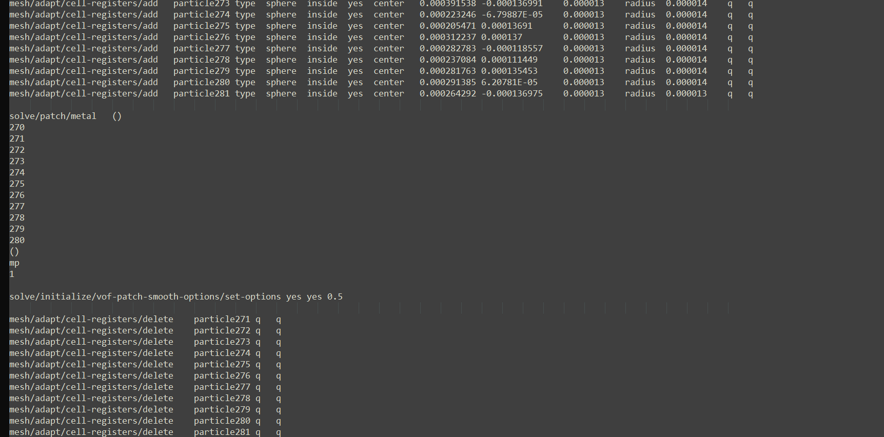 All the commands work perfectly fine but I don't understand why the number of particles created is less. I have taken a sufficiently small cell size also. The total number of particles is 281.
The image below shows the particles created which is less than the total.
 Please give some suggestion.
September 9, 2021 at 10:02 amRob
Forum ModeratorCheck for duplicates. I assume you're not initialising or patching something else in each cycle?
September 9, 2021 at 12:25 pmDubey92
SubscriberThanks for your reply. When I was patching manually, it worked really well. When I automated the process using journal, then only the issue started. And I am not initialising or patching anything else in between.
September 9, 2021 at 1:04 pmRob
Forum ModeratorWeird. Can you check what each patch operation looks like? Ie display the result after each cycle.
Viewing 41 reply threads- The topic ‘How to create the particles bed from coordinates and radii in Selective Laser Melting?’ is closed to new replies.
Innovation SpaceTrending discussionsTop Contributors-
4939
-
1639
-
1386
-
1242
-
1021
Top Rated Tags© 2026 Copyright ANSYS, Inc. All rights reserved.
Ansys does not support the usage of unauthorized Ansys software. Please visit www.ansys.com to obtain an official distribution.
-


Ansys Assistant

Welcome to Ansys Assistant!
An AI-based virtual assistant for active Ansys Academic Customers. Please login using your university issued email address.
Hey there, you are quite inquisitive! You have hit your hourly question limit. Please retry after '10' minutes. For questions, please reach out to ansyslearn@ansys.com.
RETRY


