-
-
March 13, 2024 at 2:54 am
-
March 13, 2024 at 8:57 am
Ashish Khemka
Forum ModeratorHi,
Look for a YouTube video titled:
How to change BEAM188 Line Bodies into LINK180 Elements in ANSYS Mechanical Workbench
Also, refer to the following post: how to create link180 element in TENSION in ansys workbench?
Regards,
Ashish Khemka
-
March 13, 2024 at 9:17 am
-
March 13, 2024 at 10:36 am
ErKo
Ansys EmployeeHi
It is much better and easier to have a bonded contact with a fixed contact stiffness representing the material between the two rings.
https://www.padtinc.com/2014/09/22/default-contact-stiffness-behavior-for-bonded-contact/#:~:text=If%20all%20contacts%20are%20bonded,underlying%20solid%20or%20shell%20elements.
All the best
Erik
-
March 14, 2024 at 2:17 am
Alex Li
SubscriberSorry, I didn't understand your reply.
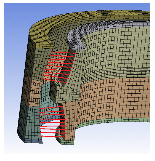
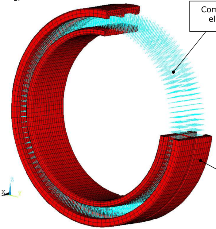
Before, I usually use link180 to simulate the roller for the SRB bearing in APDL.
Now, I start to use workbench; You know it can't use link180 directly, unless add apdl command.
So what's the best way to creat link180 or spring element and connect the nodes of the solid element. After that, how to array other rolle in the circumferential direction?
All the best
-
-
- The topic ‘How to create link180 element in workbench ?’ is closed to new replies.


-
5124
-
1831
-
1387
-
1248
-
1021

© 2026 Copyright ANSYS, Inc. All rights reserved.


