TAGGED: cfd-post, fluent, please-help, polyline, sample-points
-
-
February 18, 2022 at 5:59 am
KSD
SubscriberWe can specify number of sample points using Line tool but the same is not possible for polyline tool?
Is there any way to specify equidistant number of points along a irregular shaped 2D edge, as it is not a straight line, where we can directly use Line tool and specify the number of sample points.
In polyline, using intersection option, I am able to plot the property variation along the irregularly shaped 2D edge, but I would like to specify certain number of points in it for data comparison purpose.
Please Help.
February 18, 2022 at 8:05 amKeyur Kanade
Ansys EmployeeIn Fluent Post processing rake can be used for straight line for equidistant points.
Please check 48.2.55. Line/Rake Surface Dialog Box (ansys.com)
For polyline it is not possible in Fluent post processing. You can check CFD post for more polyline options. 12.1.10. Polyline Command (ansys.com)
Regards Keyur
How to access Ansys Online Help Document
Guidelines on the Student Community
February 18, 2022 at 5:40 pmKSD
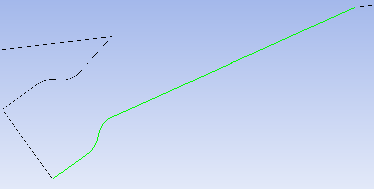
SubscriberSir, I actually want to specify 100 sample points in nozzle wall (in green color) as shown below instead of nozzle lower wall curve length

Even in Line/Rake surface you can only create straight lines by specifying two points, is there any method I can split above curved line in 100 sample points and extract data in X-Y plot.
Or in other sense can I specify the number of chart count in case of polyline (I guess there might be some way to do this)
February 21, 2022 at 11:47 amRob
Forum ModeratorYou'll struggle to get a single poly line onto the green wall. Why do you need 100 points as the solver will plot data for each facet.
February 21, 2022 at 1:04 pmKSD
SubscriberSir, I need to specify some certain number of points on that line, so that while doing grid independence test, I would get my property value at same location which will help me for comparison later on.
But now I am only able to plot using curve length as X axis which is not consistent. For e.g. if I use a coarse mesh, Fluent will consider some set of data points, but if I refine the mesh further (especially along the wall) then fluent will consider other set of points on the same wall which will later results in wrong comparison.
Even though the curve length of edge is same, but the location of points where these property has been calculated will be different which will indirectly leads to wrong meaning of Grid Independence test.
I know that interpolated curve through these random points should match, but the problem is the number of data points under Chart count very less, so interpolated curve through these points for different mesh will be slightly different.
Else the only option is to keep the number of division on that edge same and increase the mesh density in vertical direction, then only I will get same set of location of points on the green edge using Curve length as X axis.
Ok lets forget about equidistant points , are there any ways to specify set of points (x,y coordinates) on that green wall and plot the properties at that set of location.
I thought of using point cloud but in X-Y plot under location section, the point cloud is not shown.
Are there any ways to do it?
February 21, 2022 at 2:22 pmRob
Forum ModeratorIf you plot mid way between two values (ie more points on the xy plot than nodes) you're also interpolating data. So the argument about the mesh independence isn't valid. Any curve you put between points is, by definition, interpolating data so would then invalidate the data. Just plot the points and compare the effects.
February 21, 2022 at 6:32 pmKSD
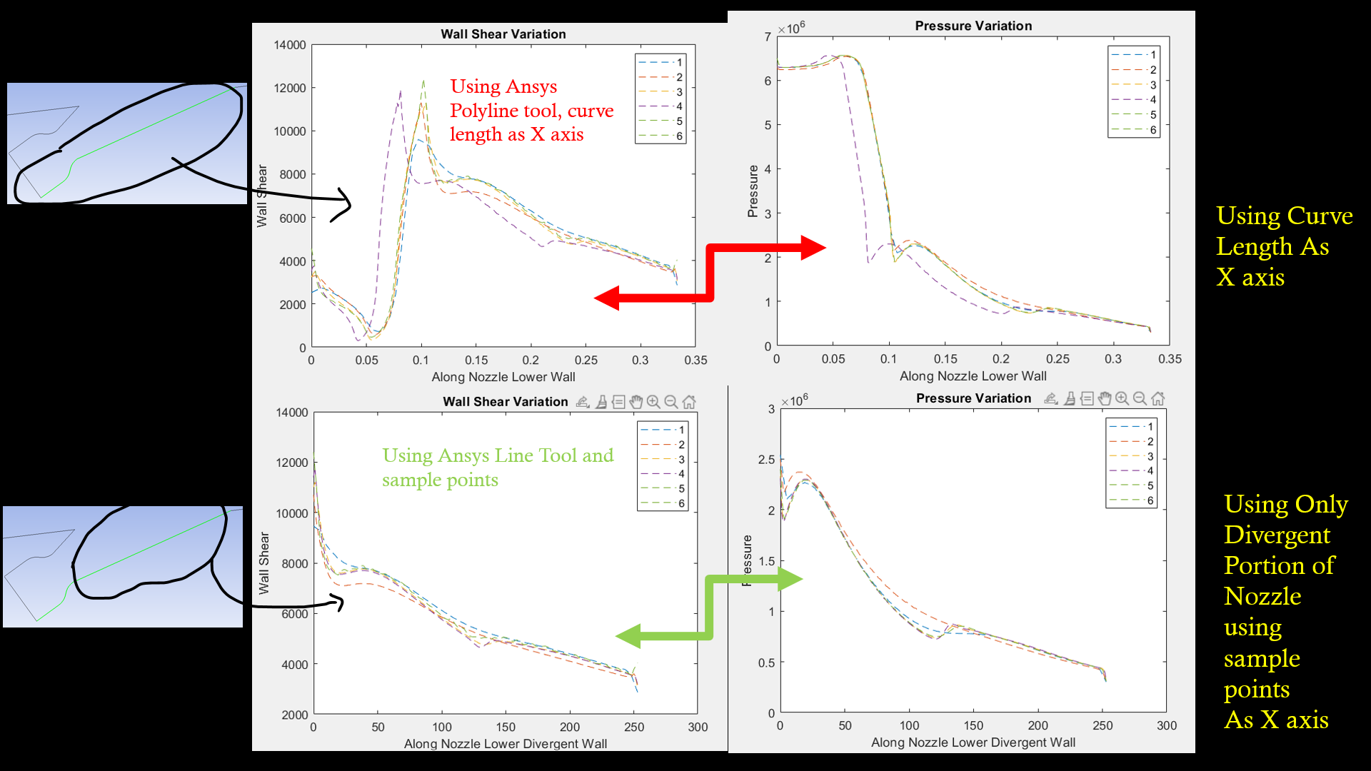
Subscriber Sir, I have plotted property variation
Case 1) Using Polyline tool and X axis as curve length for complete nozzle lower wall
Case 2) Using Line tool only for the straight divergent part of nozzle lower wall
As you can see in image there is considerable difference in plots made using by polyline tool and plots using line tool (check purple curve of both cases)
That's why I want to specify at particular location, instead at random points chosen by ansys.
Is it literally not possible to create set of coordinates and plot on that points itself?
February 22, 2022 at 4:48 pmRob
Forum ModeratorIf you plot on the wall, no polyline how does it look? Can you double check the x-position for the curve start and end points. I can understand the result being different due to separation points etc but not an off set like that. Report the domain scale (min & max values) in Fluent too.
February 25, 2022 at 5:57 amKSD
SubscriberSir, I have plotted two cases, one using polyline and intersection for whole lower nozzle wall, and second using line tool for divergent portion of lower nozzle wall.
I am not understanding what you meant by plot on wall with no polyline?
Yeah, I had checked domain extent in scale option of fluent it is same for all the cases. And also I am sure of the start and ending points of all the curve, as I have done duplication of box and just change the grid density. So rest of the things will always remain same.
Ok Sir, lets assume even that I have done some mistake somewhere else,
Still I want to know is it not possible to specify certain set of coordinates or points and plot the property value on those set of points in Ansys post processing. I think there should be some way to do this.
February 25, 2022 at 9:38 amRob
Forum ModeratorYou have a wall that has a fixed position. If you plot the values of interest against coordinate on that wall, you should see the graph you have above, but it shouldn't be possible to have an offset in x if the geometry is in the same place. With a polyline you are laying another curve over the wall, so please check it's actually in exactly the same location.
If you really want to add points to the wall edge at set distances I think you can do this by creating perpendicular lines that cross the edge. When you create the line make sure the wall is selected and you ought to get the intersection point rather than the line.
February 25, 2022 at 10:05 amKSD
SubscriberSir, yes sir you are right.
I checked the purple curve box again and it is as you said. As logically there should be drastic change in properties of flow at fix location of nozzle wall but here the location changes drastically as seen by that offset. I didn't think in that way and thought it might be related to interpolation issues.
And for perpendicular line method, it seems that I have to make n vertical lines and find the intersection of it with wall which is a herculean task. I better stick with what I have learned just now.
Thanks a lot, as always you once again helped me to clarify the issues.
Viewing 10 reply threads- The topic ‘How to create equidistant number of sample points in polyline in Fluent Post Processing?’ is closed to new replies.
Innovation SpaceTrending discussionsTop Contributors-
4673
-
1565
-
1386
-
1241
-
1021
Top Rated Tags© 2025 Copyright ANSYS, Inc. All rights reserved.
Ansys does not support the usage of unauthorized Ansys software. Please visit www.ansys.com to obtain an official distribution.
-


