
-
-
March 6, 2022 at 10:35 pm
Rameez_ul_Haq
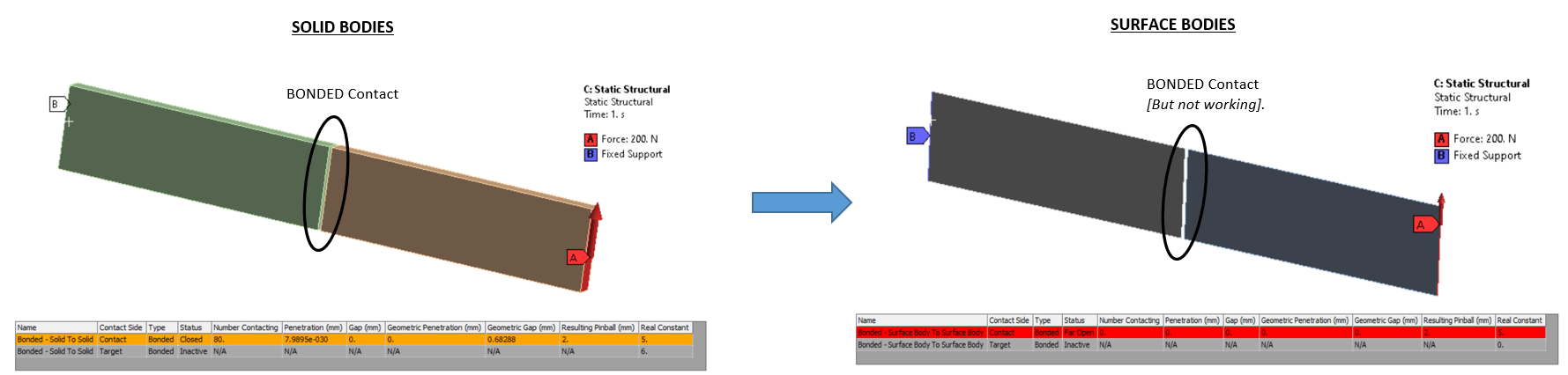
SubscriberSo I have two solid bodies (thickness of each = 2 mm) adjacent to one another, and there is a bonded contact built between them which is working properly in ANSYS. But now I want to replace these solid bodies by surface bodies (by using the Offset type as middle) and a thickness of 2 mm for each. However, whenever I try to build the bonded contact between the edges of these two surface bodies, the bonded contact is not created. Below depicts the system and what I mean.
March 8, 2022 at 1:59 pmSubscriber,I would be glad to hear your take on this issue, sir.
March 9, 2022 at 12:02 pmpeteroznewman
SubscriberIt works for me.
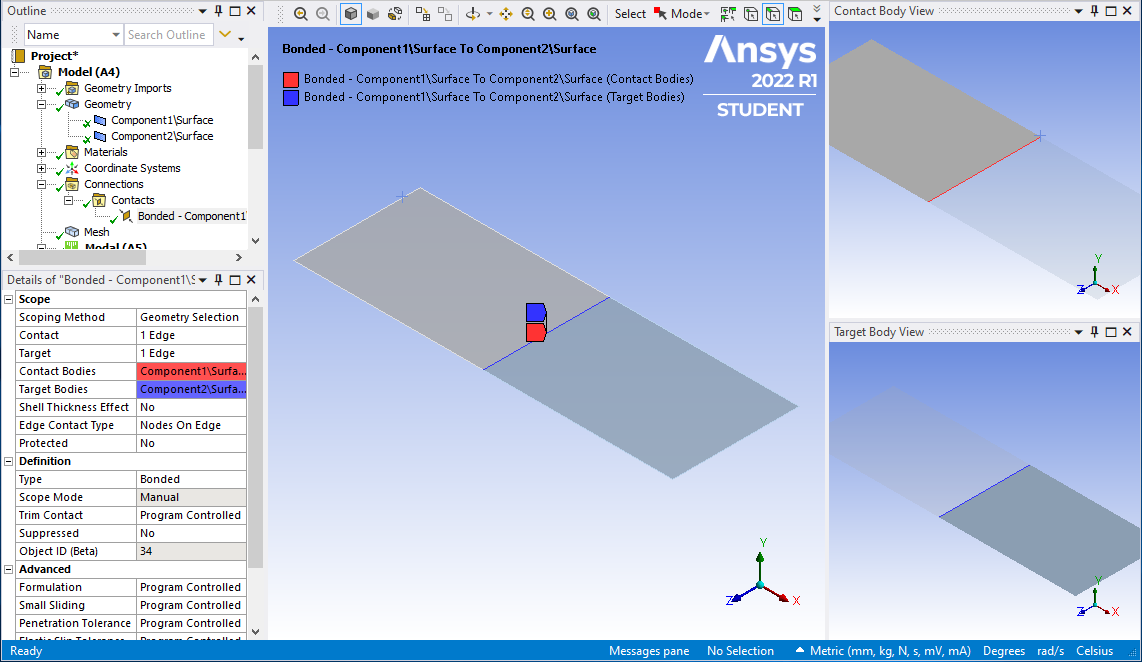
 March 9, 2022 at 7:20 pmSubscriber,I mean I don't see a gap between the connecting edges of the two surface bodies in your figure, but my model had a very small gap, if you look closely at the picture I shared. I guess it doesn't work if it has any amount of gap (i.e. gap is greater than 0 mm). Plus, for a non-linear contact, it is most likely the case that the edges connecting will have a gap initially between them, which won't make the contact to work.
So I don't know how to build a working contact between these two edges.
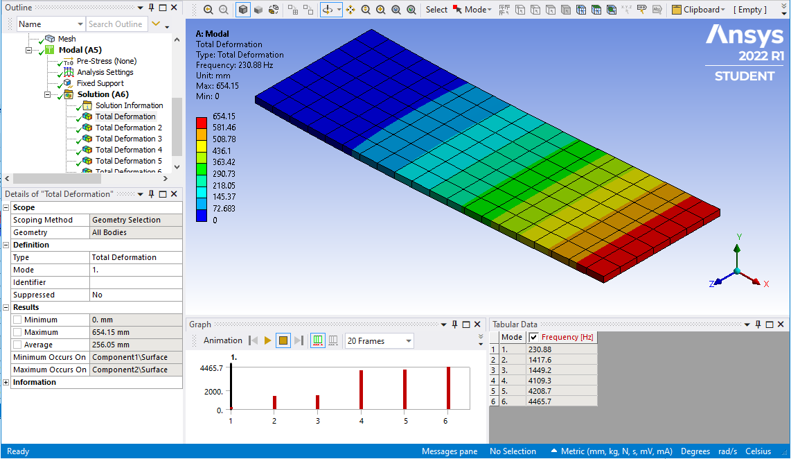
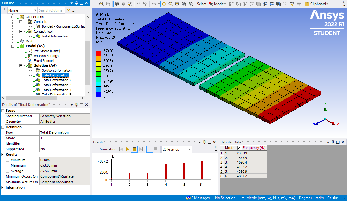
March 9, 2022 at 7:44 pmSubscriberWhen I added a gap, I also added a Contact Tool and edited the Pinball Radius to be large enough, then I got what you got, a Far Open condition even though the Pinball was large enough. I changed the Formulation to MPC, which I do for all my Bonded Contacts, then the Contact Tool showed the contact was closed.

 March 9, 2022 at 8:49 pmSubscriberthankyou. Well, for the bonded contact, I can go for MPC to close the contact between these edges.
For the non-linear contact, MPC doesn't work. So I don't know how to cope with this issue for non-linear contacts.
March 9, 2022 at 9:41 pmSubscriberI don't know if this will help, but for a frictional contact, try meshing each edge with BEAM elements. I expect the 3D contact between BEAMS is better than the 3D contact between shell edges. The BEAM elements can have zero mass and a very small value of EI because they will share nodes with shell elements that have the proper stiffness.
March 10, 2022 at 8:14 pmSubscriberTo check if BEAM elements could form a frictional contact between them or not, I did a quick example.
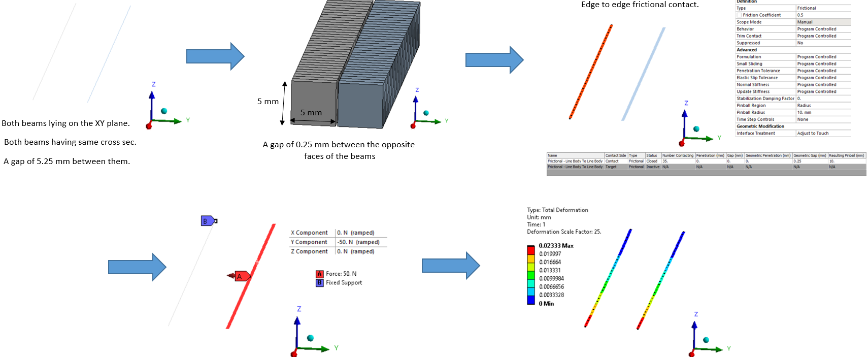 So the contact gets detected and it solves for this case, since the contact settings were changed to 'Adjust to Touch'. When I turned the force to act in X or Z direction instead of Y, it returned me a Rigid Body motion error which makes sense.
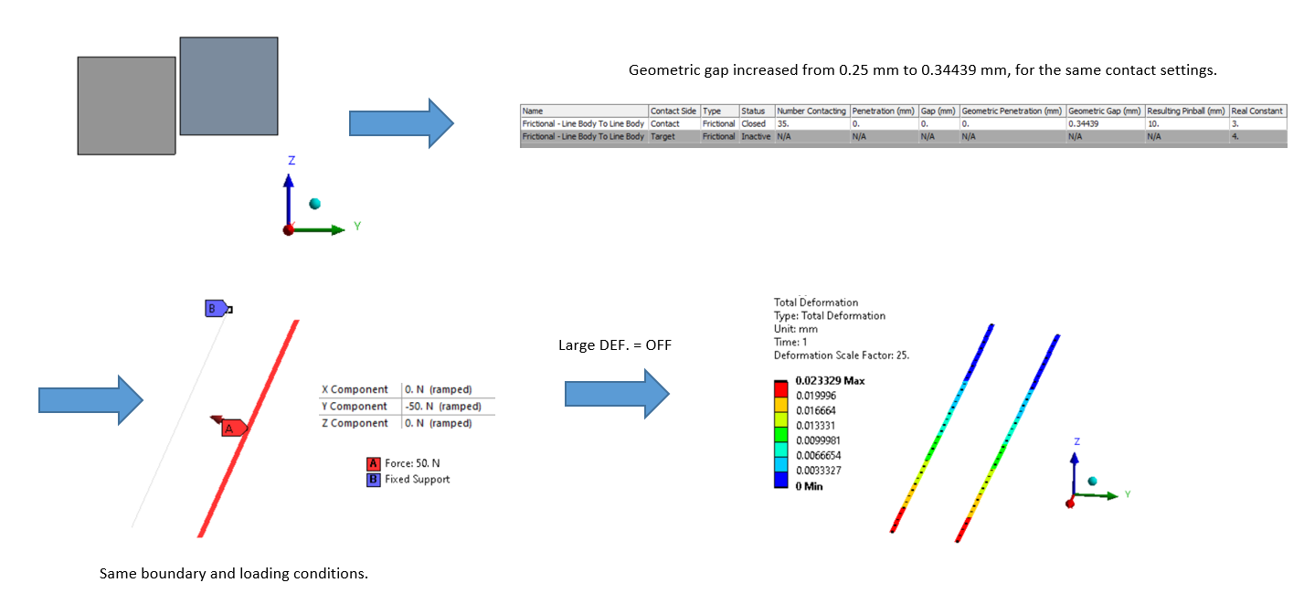
Now, I made the right body (to which the force was applied) to translate along Z axis by a distance of 1 mm, and re-conducted the analysis. Then I did the same by shifting it up by 2 mm.
TRANSLATION (along Z axis) of 1 mm :
 TRANSLATION (along Z axis) of 2 mm :
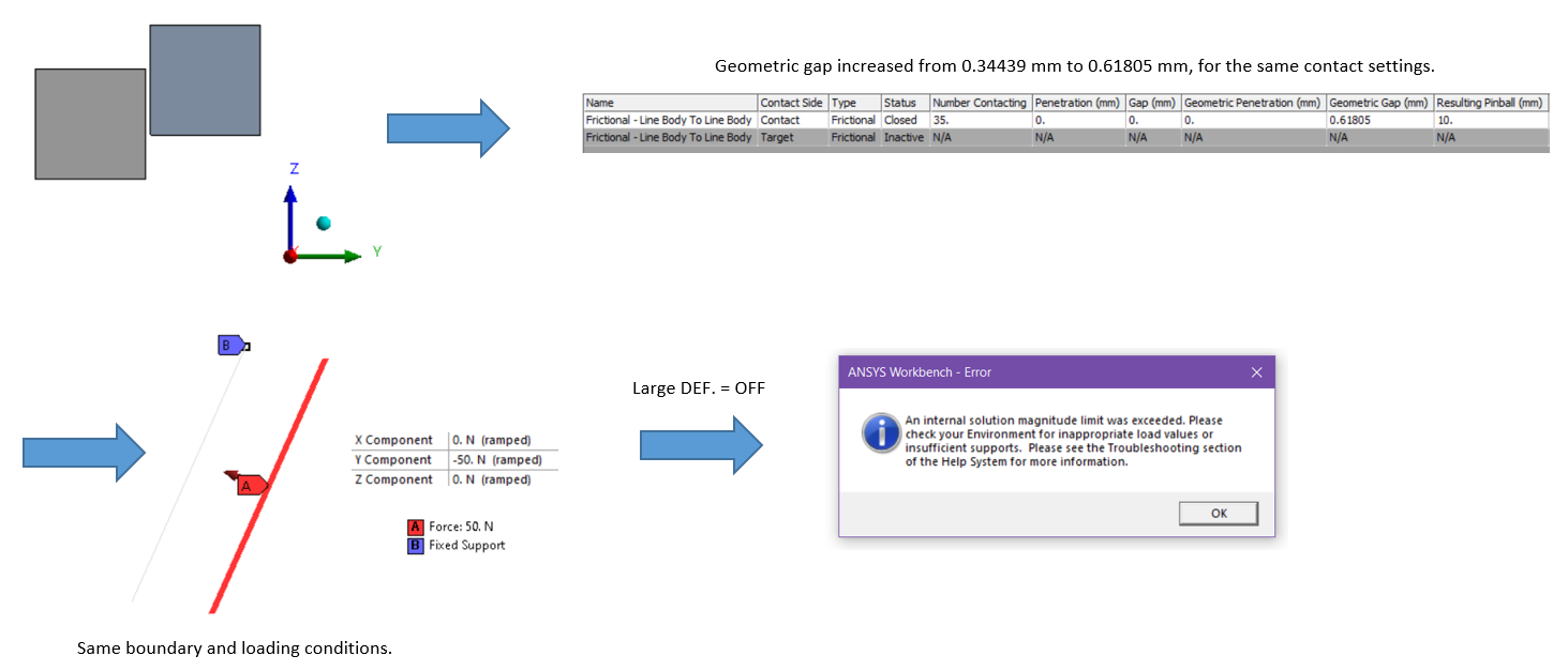 So for a translation of 1 mm, it solved, however for a translation of 2mm, it didn't solve for the same loading conditions. If it were to be solid bodies, then it would had solved for sure because there is still some part of the those faces which are in contact, which are transferring loads. But for the line bodies, it is slightly confusing. I don't know if you have had similar issues with the line bodies, but I would be so glad if I can get some information and knowledge on why does this phenomenon happen for the line bodies as shown in the images I have shared.
March 12, 2022 at 6:24 amSubscriber,I would be glad to hear your views on this one sir.
March 12, 2022 at 3:47 pmSubscriber
Surface-Surface contact algorithms were written to be very robust for the typical arrangement where element faces are facing each other.
Anytime I have frictional contact in my model, I always have element faces that are facing each other. They may be shell elements or solid element faces.
I never had a model where I needed shell element edges to make contact with shell element edges. I have used shell element edges making contact with shell element faces. This is a robust arrangement for contact algorithms also. The edge must be the contact element and the face must be the target element.
If frictional contact was needed between shell element edges, I would replace the shell elements with solid elements and then I would have solid element faces facing each other in a typical arrangement.
I haven't used 3D beam contact.
Viewing 9 reply threads- The topic ‘How to create contact between the edges of two surface bodies?’ is closed to new replies.
Innovation Space Trending discussions
 Top Contributors
-
peteroznewman
 5639
5639 -
scabo
 1885
1885 -
Dennis Chen
 1403
1403 -
javat33489
 1303
1303 -
Shyam Prasad V Atri
1021
Top Rated Tags
© 2026 Copyright ANSYS, Inc. All rights reserved.
Ansys does not support the usage of unauthorized Ansys software. Please visit www.ansys.com to obtain an official distribution.
-


The Ansys Learning Forum is a public forum. You are prohibited from providing (i) information that is confidential to You, your employer, or any third party, (ii) Personal Data or individually identifiable health information, (iii) any information that is U.S. Government Classified, Controlled Unclassified Information, International Traffic in Arms Regulators (ITAR) or Export Administration Regulators (EAR) controlled or otherwise have been determined by the United States Government or by a foreign government to require protection against unauthorized disclosure for reasons of national security, or (iv) topics or information restricted by the People's Republic of China data protection and privacy laws.
