-
-
July 26, 2021 at 4:56 pm
Awlad
SubscriberDear Support Engineers:
Is it possible that ANSYS APDL can create (or provide) the stiffness matrix? I am not asking to import the existing stiffness matrix. Rather, I want APDL to provide me the stiffness matrix? Is it possible?
I am using the *DMAT command. How could I let APDL know that I am interested to get the stiffness matrix as an output? Could you please have a look my APDL code as listed below?
!! Comment
!! Extracting Stiffness Matrix from ANSYS APDL
finish !! It will finish all previous work
/clear !! Clean woking window
/title, How to Get Stiffness Matrix?
/prep7 !! Enter to pre-processor
!! Choose a proper element type
et,1,180 !! et - element type
A=0.125 !! Area, in^2
r,1,A !! r -- real consant number
!! Define material
mp,ex,1,10e6 !! mp -- material properties
mp,prxy,1,0.3 !! mp --
!! Make FE Model, make nodes and elements
L= 10 !! L -- length, 10 inch
n,1 !! n -- making nodes
n,2,L
/pnum,node,1 !! p+num -- plot numbering
!! Make elements
!! Before making elements, we must recall ID #
type,1 !! type -- element type
real,1 !! real -- real constant
mat,1 !! mat --materials
e,1,2 !! e -- making elements by node by node
/pnum,elem,1 !! pnum -- plot numbering
eplot !! e+plot -- element plot
!! Apply BC - Boundary Conditions
d,1,all,0 !! d -- dof at nodes
!! Apply force
f,2,fx,1000 !! f -- force at nodes
alls !! all select
fini !! finish with pre-processor
/solution !! enter solution
*Dmat,Matkd,D,???
*print,Matkd,K???
solve !! solve
fini !! finish with solutions
Any suggestions will be highly appreciated. Thanks,
Awlad.
July 26, 2021 at 5:25 pmErKo
Ansys EmployeeThink this has been answered before - see also this link:https://www.ansystips.com/2017/10/export-stiffness-matrix-from-ansys.html
Even though it says import it actually reads/imports it from the full file say into a parameter (Matkd say) and then using the *export or *print it exports this matrix (Matkd) to a file.
again go through this example: https://www.ansystips.com/2017/10/export-stiffness-matrix-from-ansys.html
it is very good and clear - also refer to the help manual for *smat commands,..
Erik
July 28, 2021 at 1:35 amAwlad
SubscriberDear Mr. Erik
MANY, MANY thanks for sharing the link. It was really helpful. This is what I did to get the stiffness matrix.
First, I open ANSYS Product Launcher. I defined the "Directory (or Folder)" where all the files could be generated or saved. Then, I executed my APDL code line by line. However, I am getting an error message when I am executing the command "combine, full!! combines all file*.full into file.full".
 Yes, there is NO "file0.full" file in the Directory (or Folder)". Is this error a concern not to provide the stiffness matrix properly? Could you please let me know?
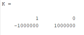
However, my APDL code generates the MatK (name of the stiffness matrix) file properly. I am using Truss element (Link180). I am also using "1 element" model. So, I have only 2 nodes. Hence, the stiffness matrix will be a (2x2) matrix. After applying the Boundary Condition, the stiffness matrix from MATLAB is as follows:
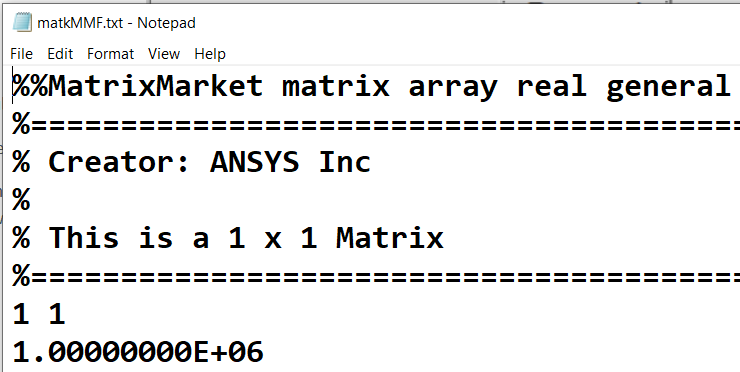
 I am using the *dmat command to create the dense stiffness matrix. Then, I am opening the MatKMMF.text file. This is what I am getting (as shown below). So, how to READ the file? Does it mean that K(1,1) = 1E6? Could you please correct me? Does APDL start the Row and Column numbers from ZERO? If so, then why I am NOT getting the K(0,0) = 1, K(0,1) = 0, and K(1,0) = -1E6? Could you please correct my understanding?

This is my APDL code. Is there anything wrong in this file?
!! Extracting Stiffness Matrix from ANSYS APDL
finish!! It will finish all previous work
/clear!! Clean woking window
/title, How to Get Stiffness Matrix?
/prep7!! Enter to pre-processor
!! Choose a proper element type
et,1,180!! et - element type
!! Define sectional properties
A=1!! Area, in^2
r,1,A!! r -- real consant number
!! Define material
mp,ex,1,10e6!! mp -- material properties
mp,prxy,1,0.3!! mp --
!! Make FE Model, make nodes and elements
L= 10!! L -- length, 10 inch
k,1!! n -- making nodes
k,2,L
L,1,2
!! Make elements
!! Before making elements, we must recall ID #
type,1!! type -- element type
real,1!! real -- real constant
mat,1!! mat --materials
esize,,1 !! ONE Element
Lmesh,all
elist
!! Apply BC- Boundary Conditions
d,1,all,0!! d -- dof at nodes
!! Apply force
f,2,fx,1000!! f -- force at nodes
alls!! all select
/solution!! enter solution
eqslv, sparse!! Equation solver
wrfull, 1!! Stops solution after assembling global matrix
solve!! solve
fini!! finish with solutions
save
/aux2!! Enters the binary file dumping processor
combine, full!! combines all file*.full into file.full
finish
! Gets Stiffness Matrix
*dMAT, MatK, D, import, full, file.full, stiff
*dMAT, Nod2Bcs, D, import, full, file.full,NOD2BCS
*print, MatK, matk.txt! Exports Stiffness to Text File
*export, MatK, mmf, matkMMF.txt
Any feedback will be highly appreciated. Thanks Awlad.
July 28, 2021 at 8:18 amErKo
Ansys Employee
Good to see that you made some progress - I have not used these commands much, so I do not know exactly how it is printed out. Perhaps someone else can help.
Finally that you get a 1x1 matrix I do not know. Obviously what you do in matlab (2D truss) and what ANsys does internally (3D spar truss) is going to be very different.
The stiffness of 1E6 is correct though (EA/L), so that is OK.
I am afraid that is all I have - good luck.
Erik
July 29, 2021 at 4:59 amAwlad
SubscriberDear Mr. Erik:
Many, many thanks. Yes, I made some progress. If any Support Engineer could answer my questions or clarify my understanding that will be highly appreciated. These are my understanding:
The stiffness matrix, provided by the *dmat command, is associated with the DOFs which are NOT constrained. For example, I made my FE model using Truss Element (Link180). I used only two nodes, Node # 1 and Node # 2. So, I have only one element, which is aligned along the global x-direction. I applied force also along x-direction. If I consider only 1 DOF (Ux) per node, then the size of global stiffness (K) matrix will be a (2x2) matrix. However, Node # 1 is fixed. Hence, the stiffness matrix, provided by the *dmat command, is NOT including the components under the "Row # 1 and Column # 1". It is providing the stiffness components ONLY under the "Row # 2 and Column # 2". So, it becomes a (1 x 1) matrix.
Then, I repeated the same simulation using 4 nodes. So, I have 3 elements. Each element is aligned along global x-direction. If I consider only 1 DOF (Ux) per node, then the size of global stiffness (K) matrix will be a (4 x 4) matrix. However, Node # 1 is fixed. Hence, the stiffness matrix, provided by the *dmat command, is NOT including the components under the "Row # 1 and Column # 1". It is providing the stiffness components under the "Row # 2 to 4 and Column # 2 to 4". So, it becomes a (3 x 3) matrix. And, those components are matching with the stiffness matrix provided by MATLAB. Here is the image of stiffness matrix provided by *dmat command.
 If any Support Engineer could clarify my understanding that will be highly appreciated. Thanks
Awlad.
July 29, 2021 at 5:52 amErKo
Ansys Employee
Have in mind that this is a forum, and not a support platform say like one would have for supported users (like ansys customer portal) - if you have a commercial licence please use the customer portal to submit a support request - also have in mind this forum does not have any "support" engineers (as this is not a standard support platform, but a forum - there are some employees from ansys that do contribute sometimes here, and when they have time, to the discussions, but the forum is really for the members to help each other.
As for your comment, during assembling of the global matrix any standard FEA software process probably/normally condenses out the fixed dof, so one would expect that the matrix would be reduced like you see.
Best of luck
Erik
July 29, 2021 at 10:46 pmAwlad
SubscriberErik:
Thanks for your comments. I spoke with my ANSYS License Manager, and I was told to post my questions in ANSYS Forum. I will follow up with my License Manager again. Thanks Awlad.
August 2, 2021 at 10:28 pmwrbulat
Ansys EmployeeHi Yes, the constraint eliminates the DOF from the system matrix, so if you comment out the line containing the D command in your one element test and rerun it, then the stiffness matrix will be a 2 X 2.
Kind regards Bill
August 3, 2021 at 5:20 pmAwlad
SubscriberDr. Bill:
Thanks.
Awlad.
Viewing 8 reply threads- The topic ‘How to Create a Stiffness Matrix in APDL’ is closed to new replies.
Innovation SpaceTrending discussionsTop Contributors-
4708
-
1565
-
1386
-
1242
-
1021
Top Rated Tags© 2026 Copyright ANSYS, Inc. All rights reserved.
Ansys does not support the usage of unauthorized Ansys software. Please visit www.ansys.com to obtain an official distribution.
-


Ansys Assistant

Welcome to Ansys Assistant!
An AI-based virtual assistant for active Ansys Academic Customers. Please login using your university issued email address.
Hey there, you are quite inquisitive! You have hit your hourly question limit. Please retry after '10' minutes. For questions, please reach out to ansyslearn@ansys.com.
RETRY


