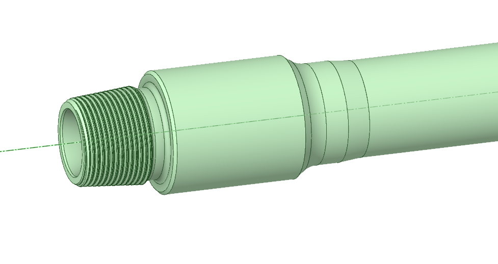
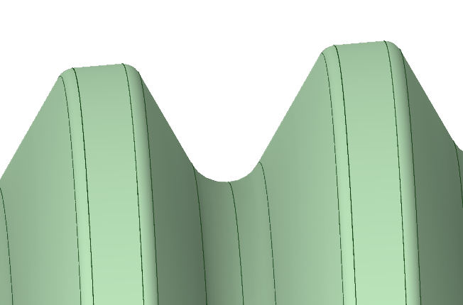
I suggest you use tetra elements. Making hexa elements on a spiral shape is very difficult. It's difficult on the outside, like your picture shows. You have to make one 360 section so that it matches periodically, then copy to the other threads, then make the rest. Meshing inside a spiral, which looks to be your model, is even more difficult because the spiral grid lines need to all meet up at the center somehow, which they can't so you need to make structured or unstructure interrupts at some location around each 360 of each thread. SpaceClaim meshing has the means to create the "blocking" that manually structures mesh like this, but it would take a lot of time to get up to speed learning and then applying it in your model. I don't suggest it.
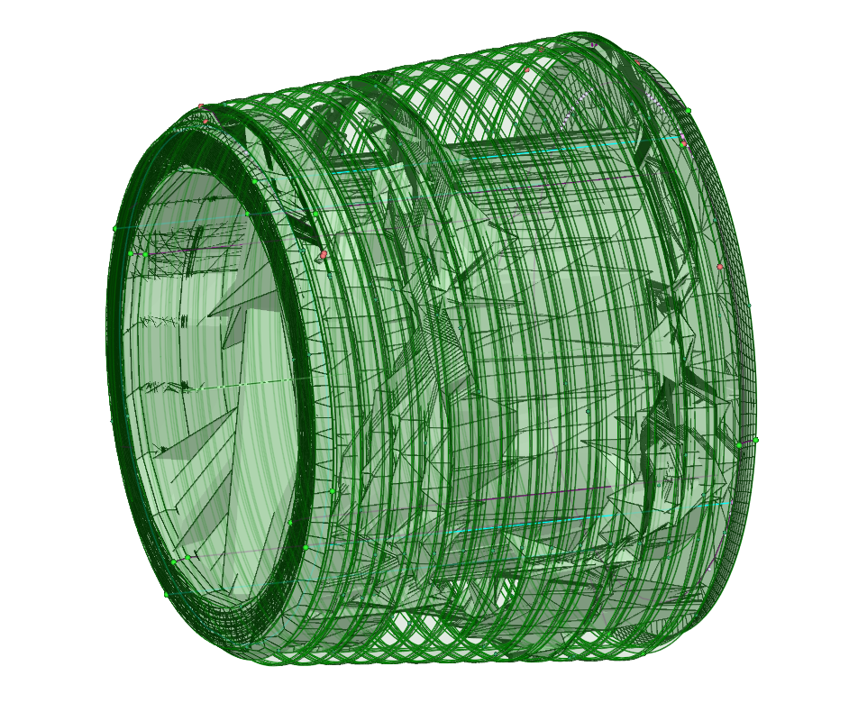
So I definitely recommend tetra meshing. Your tetra mesh shows huge elements which is either from an error in meshing, or you need to set smaller face and/or edge sizings. I have had trouble with long thin spiraling or long path-tracing faces before with the patch conforming tetrahedral mesher. The easiest soluton is to switch to the patch independent tetra mesher, but it has a few drawbacks. One is that you wait longer for the meshing to complete. If you want to use the faster patch confroming tetra meshing, try making a plane along the axis of the bolt, and split the faces along this plane in the geometry modeler. You don't need to split the body, just the faces. This means you will have a bunch 180 degree wrapping faces, not he current thread faces that wrap 360xn where n is the number of threads. If you don't want to go back to the geometry modeler, you could use Virtual Topology in Mechanical to split the faces. You need to split the edges first, also with virtual topology. But this would take a good deal of time, since you have a lot of threads.