TAGGED: constraint-issue, coupling, shell-and-tube
-
-
October 29, 2021 at 9:41 am
manuel.uruena
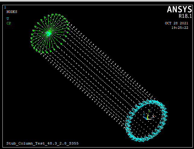
SubscriberI am modelling a hollow tube with shell elements for a stub column test.
I want to apply the loads/displacements to a central node at the top instead of to the edge of the tube.
The central node is the master node, and the nodes at the edge are the slave nodes.
When solving, I get the error "Specified degree of freedom constraint at unused node". I understand this is because the master node is not attached to any element.
How can I solve this error? I want the load/displacement applied to the master node to be transferred to the nodes at the edge of the tube.
October 29, 2021 at 10:10 amErKo
Ansys EmployeeHi
Use RBE3 (small deflections only), or CERIG (small deflections only) or MPC184 elements (or MPC contacts to do the load transfer).
See the help manual for possible examples and explanation of these commands (the web should have quite a lot of info also).
Thank you
Erik
October 29, 2021 at 10:30 ammanuel.uruena
SubscriberDear ekostson I have tried both REB3 and CERIG, and either they both give me an error. I am using large deflections (NLGEO). I think the problem is not the coupling but the fact that the node is "unused".
Thanks
October 29, 2021 at 10:56 amErKo
Ansys EmployeeHi
Since you are using large defections, you cannot use CERIG RBE3 (they are only for small deflections).
So you have to use MPC contact elements or MPC184 elements (a spider wheel is needed like you show in the CP image in your first post) for that see this helpful post on how to define them (mpc184 "spider" wheel).
All the best of luck
Erik
Viewing 3 reply threads- The topic ‘How to couple nodes to an unused node and applied a load to it?’ is closed to new replies.
Innovation SpaceTrending discussionsTop Contributors-
4909
-
1598
-
1386
-
1242
-
1021
Top Rated Tags© 2026 Copyright ANSYS, Inc. All rights reserved.
Ansys does not support the usage of unauthorized Ansys software. Please visit www.ansys.com to obtain an official distribution.
-
The Ansys Learning Forum is a public forum. You are prohibited from providing (i) information that is confidential to You, your employer, or any third party, (ii) Personal Data or individually identifiable health information, (iii) any information that is U.S. Government Classified, Controlled Unclassified Information, International Traffic in Arms Regulators (ITAR) or Export Administration Regulators (EAR) controlled or otherwise have been determined by the United States Government or by a foreign government to require protection against unauthorized disclosure for reasons of national security, or (iv) topics or information restricted by the People's Republic of China data protection and privacy laws.


