-
-
March 9, 2020 at 9:41 am
adityaparpe
SubscriberHello.
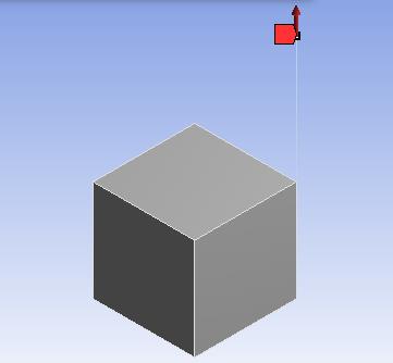
Actually, I am doing modelling of a concrete cube from which steel rebar is attached and I have attached a spring element between one node of the cube and one node of rebar element. But when I run the model, the following error is coming:
There is at least 1 small equation solver pivot term (e.g., at the UZ
degree of freedom of node 1). Please check for an insufficiently
constrained model.
Please help me to fix this error
-
March 12, 2020 at 2:22 pm
SaiD
Ansys EmployeeHello,
The error suggests that the rigid body displacement in z-direction might not have been constrained. Could you check that all the rigid body displacements and rigid body rotations are constrained? If that does not help, could you share more details about the geometry and boundary conditions?
Thanks,
Sai
-
March 14, 2020 at 7:08 am
adityaparpe
SubscriberThank you for the reply, I appreciate that.
Actually, I have made a concrete cube in which a steel bar is connected at one of the nodes and the base of a concrete cube is fixed. The other end of rebar is subjected to axial force. But when I run the model, this error comes. Please help me with this.
-
March 16, 2020 at 2:13 pm
SaiD
Ansys EmployeeIs the steel rebar meshed using truss elements or using beam elements? Because truss elements don't have any stiffness in lateral directions, they only have non-zero stiffness in the axial direction. So if truss elements are used, in the figure above, is there any boundary condition to prevent the bar from rotating i.e. is there any resistance to lateral motion of the top node?
-
March 16, 2020 at 2:36 pm
adityaparpe
SubscriberFrom where should I change that meshing is done using truss elements or beam elements? But I gave the properties of LINK180 to steel rebar. please help me with this.
-
March 20, 2020 at 1:29 pm
SaiD
Ansys EmployeeIf you don't expect the steel rebar to show any deflection in the lateral directions (i.e. directions normal to its axis), you can set the displacement in those directions to be 0. That should provide sufficient constraint.
Hope this helps,
Sai
-
- The topic ‘How to correct this error?’ is closed to new replies.


- The legend values are not changing.
- LPBF Simulation of dissimilar materials in ANSYS mechanical (Thermal Transient)
- Convergence error in modal analysis
- APDL, memory, solid
- How to model a bimodular material in Mechanical
- Meaning of the error
- Simulate a fan on the end of shaft
- Real Life Example of a non-symmetric eigenvalue problem
- Nonlinear load cases combinations
- How can the results of Pressures and Motions for all elements be obtained?

-
4062
-
1487
-
1308
-
1156
-
1021

© 2025 Copyright ANSYS, Inc. All rights reserved.


