TAGGED: transient-structural
-
-
July 18, 2023 at 2:12 pm
tirth.a2021
SubscriberHi,
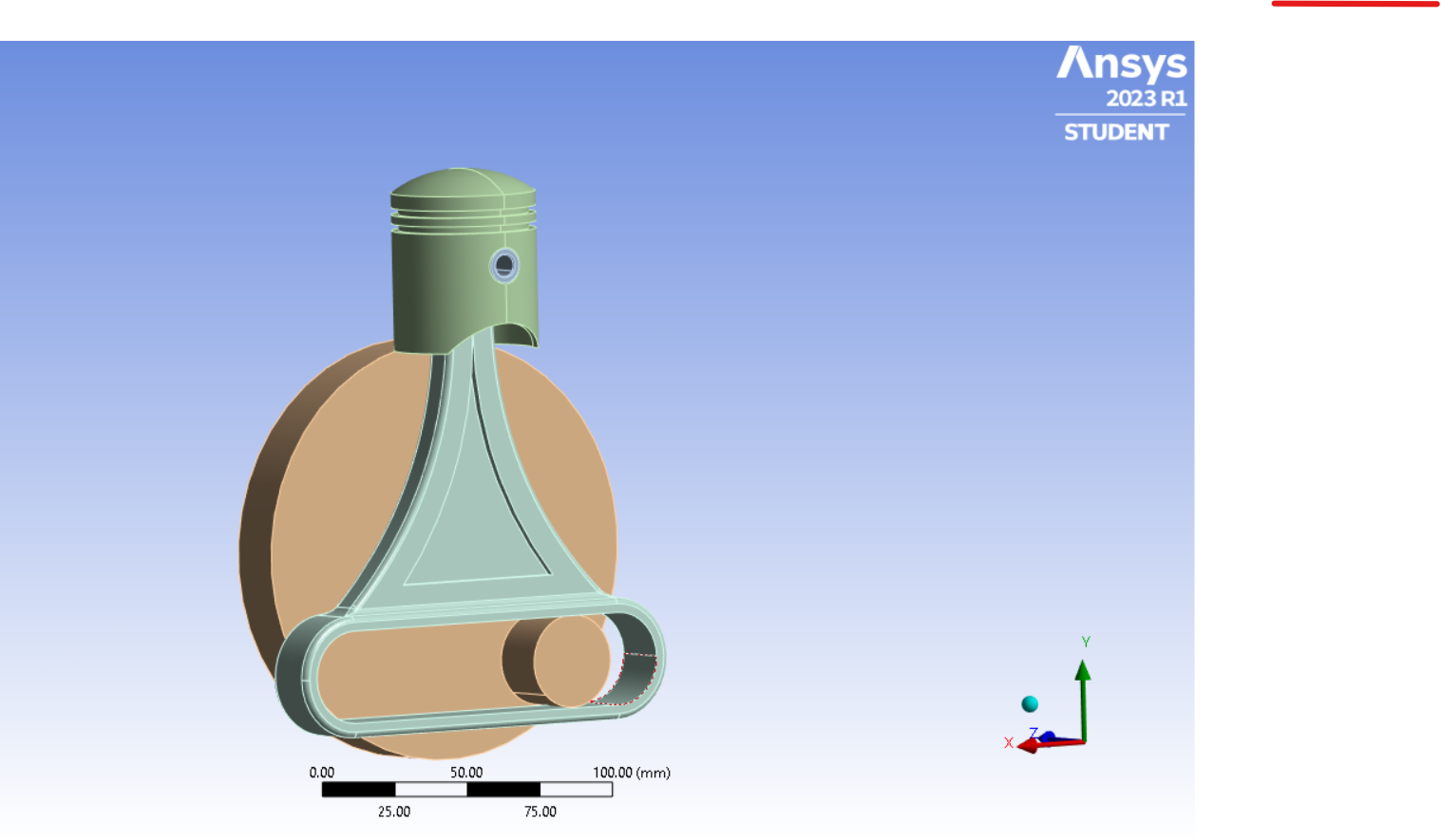
So I have a model of a scotch yoke mechanism based piston cylinder as shown, on which I intend to perform a Transient structural analysis.
The crank has a cylindrical extrusion (Lets call it a roller, although I dont intend it to rotate) that moves inside the slot of the connecting rod. So while the crank rotates, the piston has a reciprocating motion. I then tried adding the joints for this assembly and that is where I have an issue.
When I try allocating a Translational joint to the roller and the slot, the reference system that shows the direction of motion is inclined due to a certain edge on the cylinder. Note this that my CAD model does not contain the "edge", whereas ANSYS shows it. Its shown below:
So while I want to give the roller a translation motion inside the slot, along the length of the slot, I rather end up with an inclined direction that fails the purpose, shown in next screenshot.
Can you please let me know how I can set it so that the direction of translation of the roller (X-axis) is along the slot length. Or if there's any other way.
BTW I'm using a workbench 2023 R1. Appreciate any help I can get.
Thanks! -
July 19, 2023 at 10:01 am
Aniket
Forum ModeratorSo do you intend to rotate the disk with the "roller" around the bottom disc's center point or will you be sliding the roller in the slot?
-Aniket
-
July 20, 2023 at 6:02 pm
tirth.a2021
SubscriberWell both actually. You see, primarily the disc would be rotating and the roller along with it. But since the roller is constrained inside the slot, it will impart vertical forces to the connecting rod so that it rotates with the disc, as well has slides inside the slot.
-
-
July 22, 2023 at 12:57 pm
peteroznewman
SubscriberWhat is the connection between the piston and connecting rod? I see a pin through the piston. If you have rotational freedom of the connecting rod to the piston at that pin, that would be a mistake.
The link with the slot in a Scotch yoke mechanism must have only translational freedom and all other DOF must be constrained.
If the piston, pin and connecting rod are bonded together, you could add a Translational Joint to ground on the Piston so that it can only travel along the Global Y axis.
The disk would have a Revolute Joint to ground.
Use Frictional or Frictionless Contact between the slot faces and the roller.
It doesn’t matter that there is an edge on the roller face, but if you open the geometry in SpaceClaim, on the Repair tab, click Extra Edges and it will delete that edge.
-
July 22, 2023 at 1:21 pm
tirth.a2021
SubscriberThanks for your reply! I'll make the changes you mentioned and try removing the edge like you said. Thanks!
-
-
- The topic ‘How to correct direction of Translation joint for transient structural analysis?’ is closed to new replies.


-
4683
-
1565
-
1386
-
1242
-
1021

© 2025 Copyright ANSYS, Inc. All rights reserved.


