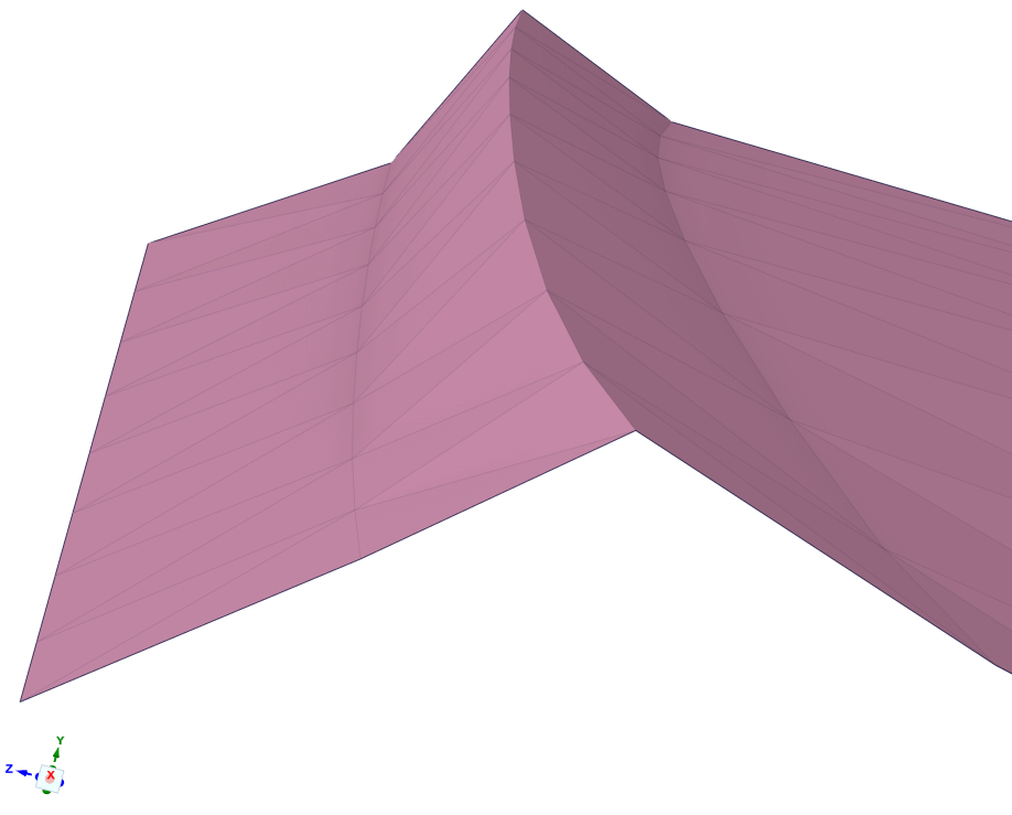
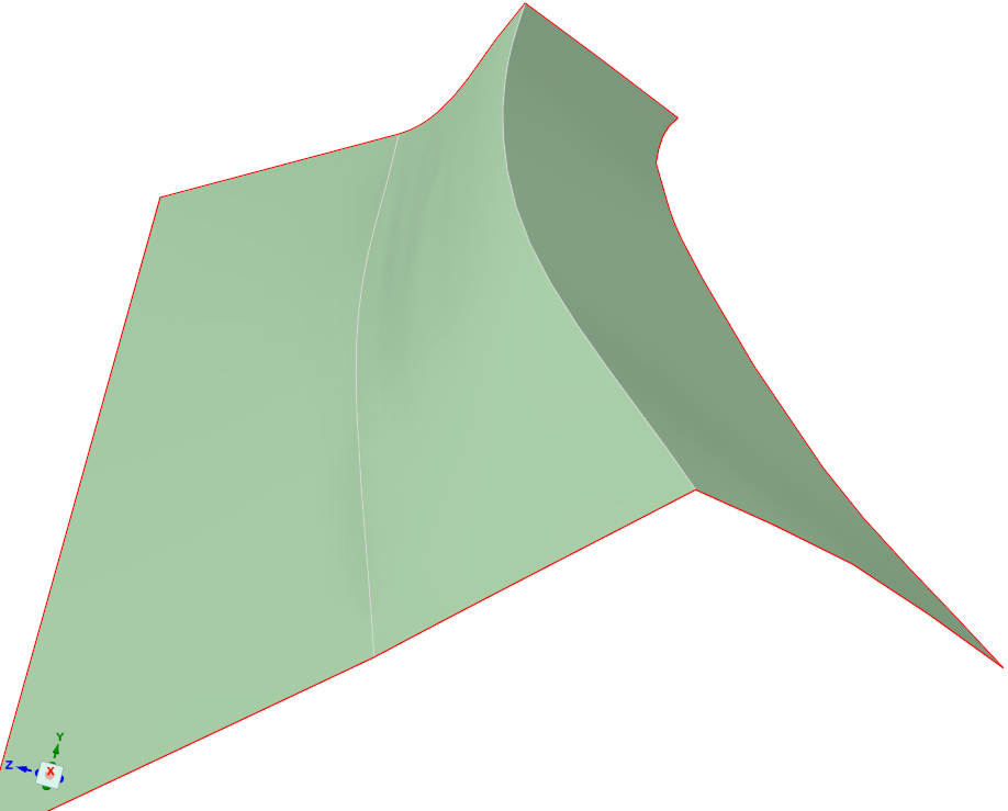
-
-
March 28, 2023 at 9:15 pm
Aras karimi
SubscriberHello Ansys community,
I have the geometry STL file and I am going to convert it to solid geometry by SpaceClaim software and get an Export in STEP format from it. First, I Imported the STL file in SpaceClaim, then I selected the Auto-Skin option from the Tools tab and selected the geometry, but I received an error. What steps do you suggest so that I can do this ?
-
March 29, 2023 at 1:03 am
peteroznewman
SubscriberHello Aras,
Are you using the free Ansys Student license? If so, you can't export STEP files.
You need a full license such as a Research or Commercial license to export STEP files.
-
March 29, 2023 at 8:34 am
Aras karimi
SubscriberI am using Ansys version 2022 R1 and its license is not a free student license and it is full.
What should I do now?
-
March 29, 2023 at 12:14 pm
-
March 29, 2023 at 7:58 pm
Aras karimi
SubscriberThank you for your educational videos.
But I failed to convert the STL file into solid geometry and finally Export it as an STP file. Is it possible to send the STL file of the geometry that you can help me with ?
I have been involved in this issue for a long time.
Thankyou
Regards. -
March 29, 2023 at 8:04 pm
peter.newman
SubscriberAras, compress the STL file into a .zip file. Upload the .zip file to a file sharing site such as Google Drive or OneDrive. Reply with a link to the file.
-
March 30, 2023 at 8:12 am
Aras karimi
Subscriberhere you are
Thanks.
-
-
March 30, 2023 at 11:29 am
peteroznewman
Subscriber-
March 30, 2023 at 4:55 pm
Aras karimi
SubscriberI think you can access it now. Did the link open for you ?
-
-
March 30, 2023 at 5:18 pm
peter.newman
SubscriberYes, I have it now. I will try out some things and give you a solid body to look at in a day or two.
-
April 1, 2023 at 8:16 am
Aras karimi
SubscriberHi peteroznewman,
have a good time
Did you manage to convert the STL file into solid geometry and get an Export from it in STEP format ?
-
April 1, 2023 at 2:27 pm
peteroznewman
SubscriberAras, starting to work on it now.
STL files don’t have units so you can assign any unit to the numbers in the file: mm, inches etc. What units should I use with this file?
It was automatically assigned mm.
Success!
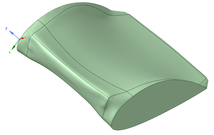
Below is a link to the SpaceClaim 2022 R1 file. You can export the STEP file from SpaceClaim.
-
April 2, 2023 at 9:40 am
Aras karimi
SubscriberThe main geometry dimensions are in millimeters. When importing the STL file into SpaceClim, I tried all the units, including mm, cm, meter, inch, and automatic mode, but I did not see any change in the opened geometry. With these interpretations, should the unit type be determined when importing the STL file into SpaceClim ?
-
April 2, 2023 at 10:11 am
Aras karimi
SubscriberThank you for the geometry you created.
I've seen the spaceclaim file of the solid geometry, but the geometry is made up of a number of separate surfaces, and the interior of the geometry is also filled. Is it possible for the geometry to have a completely continuous and integrated surface and not be filled interior and be in the form of a shell like the original geometry (STL file) ?
If you could please send me the training video of the process of converting the STL file to solid geometry, I would really appreciate it.Regards.
-
April 2, 2023 at 11:15 am
peteroznewman
SubscriberIf I select the units of Inches in the File Open dialog when opening the STL file, I get a very different dimension for the wing.
You can easily change the solid body into surfaces. In the Structure panel on the left side where you see the Patch Body solid, right click on that and select Detach All. Now you have all the individual surfaces and no interior. Click on the graphics screen the surface you want to delete and then hit the Delete key. Now you have surfaces that are close to the original STL file.
It is not possible to merge these faces into a single surface. The mathematics used to represent them (NURBS) has limitations on the shapes it can represent, which is why the AutoSkin tool segments the STL body into patches to fit the surfaces.
Why do you need a single surface? What are you going to use this geometry for? Are you going to mesh it for analysis? You can cut a patch into smaller pieces if that is helpful. Or is it just for appearance? You can turn off the edge display.
You can use an Opaque style.
-
April 2, 2023 at 3:10 pm
Aras karimi
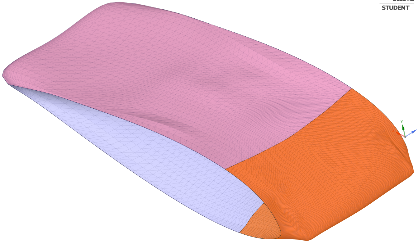
SubscriberIn the Structure panel on the left side, I right clicked on the Patch Body and selected Detach All, and I deleted the front and back surfaces of the wing that closed it, and this is what it looked like
Now the upper and lower surface of the wing is composed of several separate surfaces. I want the upper and lower surface of the wing to be a completely connected surface and not to be composed of several separate surfaces , Because I want to take an Export in STP format from SpaceClaim and open it in Design Modeler and do a series of drawings there and then take it to the Meshing software for analysis. Therefore, the geometry STEP file that I Export from SpaceClaim should be one surface and not several pieces of surface.
Is it possible to convert the pieces of the upper and lower surfaces of the same geometry that I sent into a connected and integrated surface and merge them together ?
-
April 2, 2023 at 7:44 pm
peteroznewman
SubscriberYou want to make some drawings. Drawings show 2D views of 3D objects. You can take a series of Planes and Split all the surfaces with the Planes, then you will have a planar series of Curves to put on a drawing view. You can hide all the surfaces and show only the Curves and the boundary between surfaces will not be visible.
You don’t need a single surface for analysis, the mesh will be connected across adjacent surfaces if in SpaceClaim, you go to the Workbench tab and hit the Share button. This creates shared topology that causes adjacent surfaces to share a common edge. You can also create shared topology in DesignModeler.
Finally, you don’t need to export to a STEP file in order to open the file in DesignModeler. Place a Geometry component on the Project page of Workbench. Right click and Browse to open the SpaceClaim file, then you can right click to Open in DesignModeler.
-
April 3, 2023 at 3:17 pm
Aras karimi
SubscriberYour first paragraph: Unfortunately, I did not understand your first paragraph.
I don't plan to draw on the wing in Design Modeler, I just want to draw the domain for analysis around the wing.Your second paragraph: In the figure below, why is it not possible to combine these 8 Surface and convert them into 1 single Surface and finally get an Export in STEP format ?
I mean the Single Surface is exactly the same as the figure you posted above, that is, this figure:
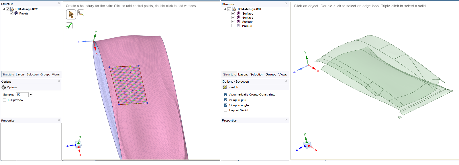
I went to the Workbench tab and clicked on the Share button, then the following form was created:
What should I do next ?
Your third paragraph: I didn't understand the explanation of this part exactly and I don't know when I should do it.
I am totally confused and I don't know exactly how and when I should do the steps to achieve the final success.
If you please, teach me how to convert the STL file to solid geometry and then merge 8 Surface into 1 single Surface and how to open it in Design Modeler or how to Export the geometry STEP file in the form of a video tutorial.Thank you
Regards.
-
April 3, 2023 at 7:44 pm
peteroznewman
SubscriberWhen I read drawing, to me that meant taking a 3D object to make 2D views of it to plot on paper or export to a 2D file format, but what you explained in your reply is that you want to construct a domain for analysis. Aras, it will be better if I know the end goal of your project. I guess you want to create a CFD model and compute the Lift and Drag Coefficients.
Tell me more about the domain. Is the domain supposed to represent open air or flow in a duct? Tell me more about the wing. Is the air supposed to enter through the open holes on each side and swirl around inside? I would have expected that the end faces would be capped off to prevent that. If that is true, then you are better off keeping the original solid and subracting that from a large block of air. What is the fluid velocity coming at the wing? What angles does the flow come at the wing?
To make a domain of air to mesh around that wing shape: 1. you don’t need to combine the surfaces into one surface, 2. you want a solid body, you don’t want the surfaces with holes in the ends. 3. you don’t need a STEP file. Furthermore, it is possible to create a mesh directly around the STL file, though I am not as skilled at that workflow as it relies on Fluent meshing and I am skilled at Ansys meshing.
Watch some YouTube videos on the workflow to mesh the air domain for a 3D flow simulation to get an idea of the steps. Then post a new Discussion to get help on the overall goal.
-
April 4, 2023 at 9:50 am
Aras karimi
SubscriberYes, I want to create a domain for analysis in Design Modeler, then take it to the Meshing software and use Fluent to calculate the aerodynamic coefficients.
The domain that is supposed to be created in the Design Modeler is in the shape of a rectangle from which the wing is Subtracted and the flow passes over it.The purpose of the flow is to pass over the wing, no flow will pass through the open holes on either side. You are right, we should keep the solid original in the spaceclaim and then subtract it from the domain in the Design Modeler.
Did you create the solid model inside the SpaceClaim in a Filled form or Did you only close its front and back surfaces ?
You are right we want a solid body and We don’t want the surfaces with holes in the ends.To create a domain in Design Modeler, I Exported the same Spaceclaim file that you sent me without any changes and without removing the front and back surfaces, in STEP format and opened it in Design Modeler.Then I drew the domain around the wing and finally I subtracted the wing from the domain, which is as shown in the following figure:
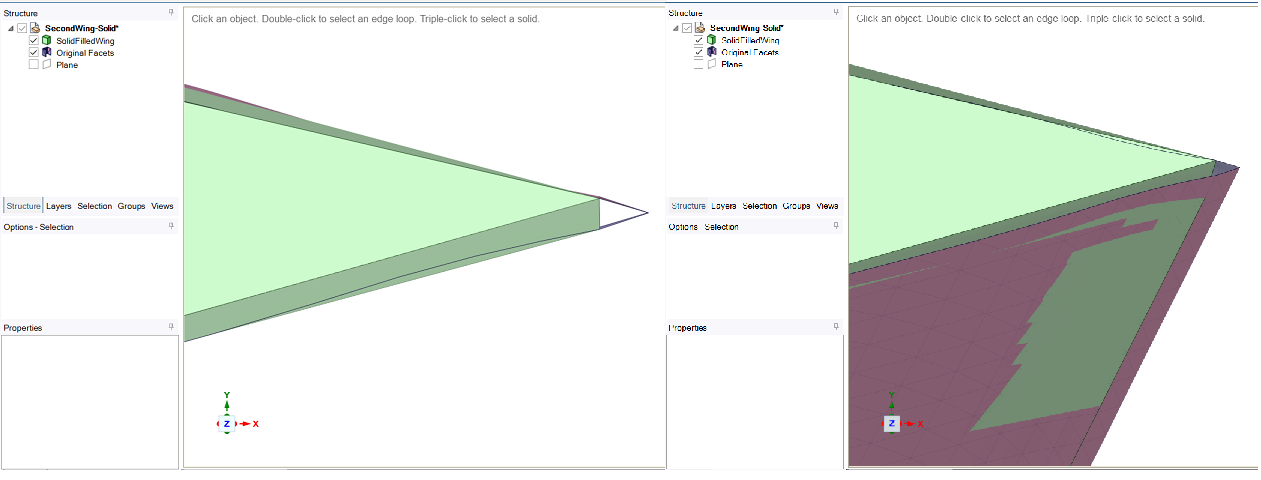
Now the problem is as shown in the figure below, by selecting the front surface of the domain, a piece of the front part of the wing is also selected, as if the wing is not completely removed from the domain :
I think that the patchiness of the upper and lower surfaces of the wing caused the problem. Therefore, the upper and lower surfaces of the wing must become a single surface.
I don’t know anything about being able to mesh the STL file, and I think it would be more routine to Export the geometry in STEP format from SpaceCalim.
I am familiar with the process of simulating 3D flows. After drawing the domain in Design Modeler, we can refer to one of the Meshing softwares and finally use Fluent to solve the flow.
Eventually,
In Spaceclaim, I need the Wing in the form of a solid body with a filled inside and all its surfaces are a single surface and not created from several pieces of surfaces, so that I can Subtract it from the domain without problems in the Design Modeler. -
April 4, 2023 at 10:00 pm
peteroznewman
SubscriberWhy does the air domain end at the flat ends of the wing? Is this wing to be tested in a wind tunnel with walls touching the left and right faces of the wing? That is what you have. Or is the wing to be tested in a larger volume of air that extends beyond the left and right faces of the wing? This is what I would expect you would want to test. A lot of interesting flow phenomina occur beyond the tip of a wing. Make the width of the block at least ten times wider than the width of the wing. That is a minimum to study flow over a wing, a width twenty times the wing width is better.
You do not need to convert the wing to a single surface. The mathematics used to represent the shape do not allow a single surface to represent that shape. There will be no problem meshing the air with a solid wing made up of multiple surfaces. If any problem is found with the element quality during meshing, it will be improved by dividing the air domain up into pieces, possibly dividing the wing into pieces, adding to the total number of surfaces on the wing.
The SpaceClaim document was a solid (filled) body. There is no need to export a STEP file. DesignModeler can open a SpaceClaim file.
-
April 5, 2023 at 6:41 pm
Aras karimi
SubscriberDue to the boundary condition used, the width of the domain must be equal to the width of the wing.
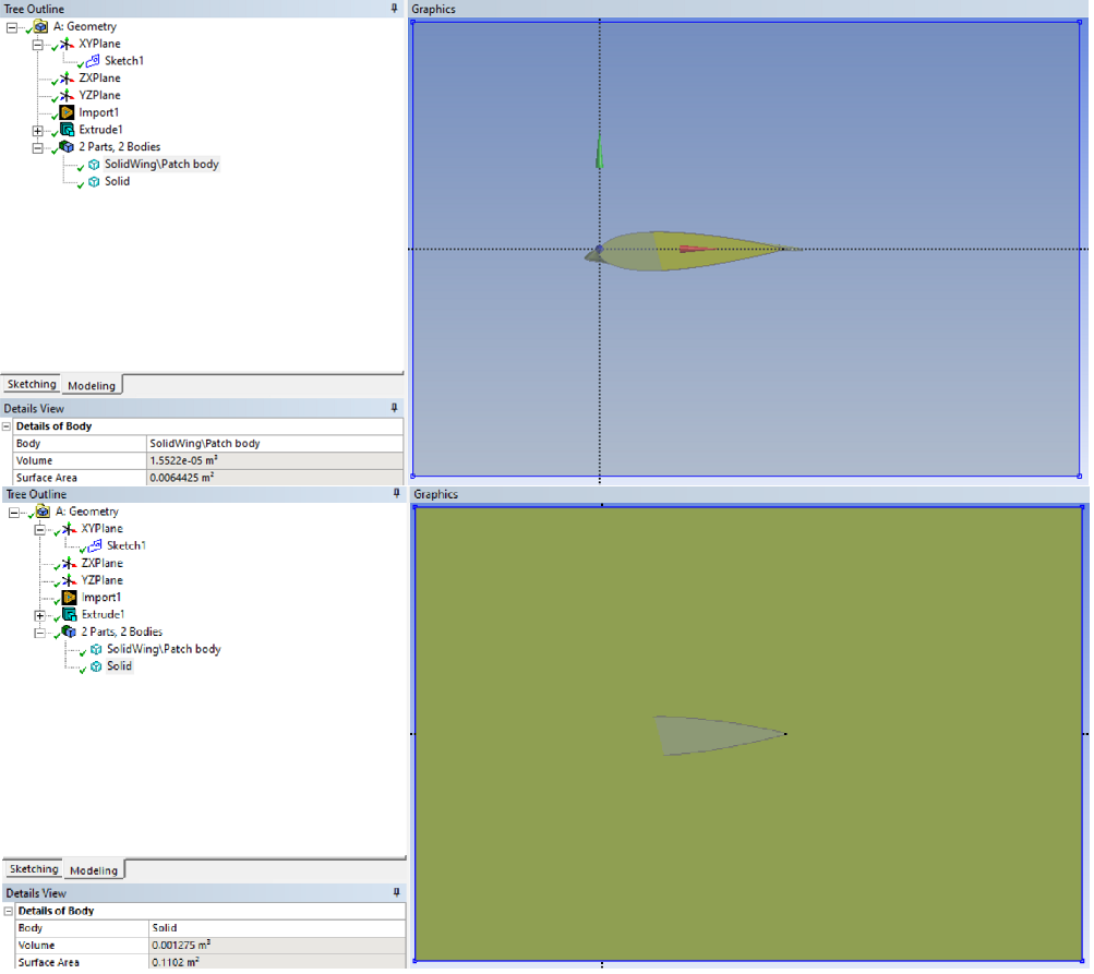
Before I subtract the wing from the domain, selecting the air domain once and the wing once from the Design Modeler tree diagram gives a representation like this:As you can see, such a representation of geometry looks wrong and indicates a problem with geometry.
I think that this representation of the fragmented surface of the solid wing, which is provided by the mathematics used, is not just a representation, but actually the geometry of the STL file has been transformed into a solid body by connecting several pieces of the surface to each other, and it is very strange that Multiple levels cannot be merged.
Fragmentation of the wing surfaces creates many lines that are the boundary between the surfaces, which is misleading and creates problems for the meshing process.
Is there no way to make the wing a single surface ?This figure (figure below) that you sent me earlier that showed a single surface for the wing , does it still show a single surface after importing it into Design Modeler ?
-
April 5, 2023 at 10:28 pm
peteroznewman
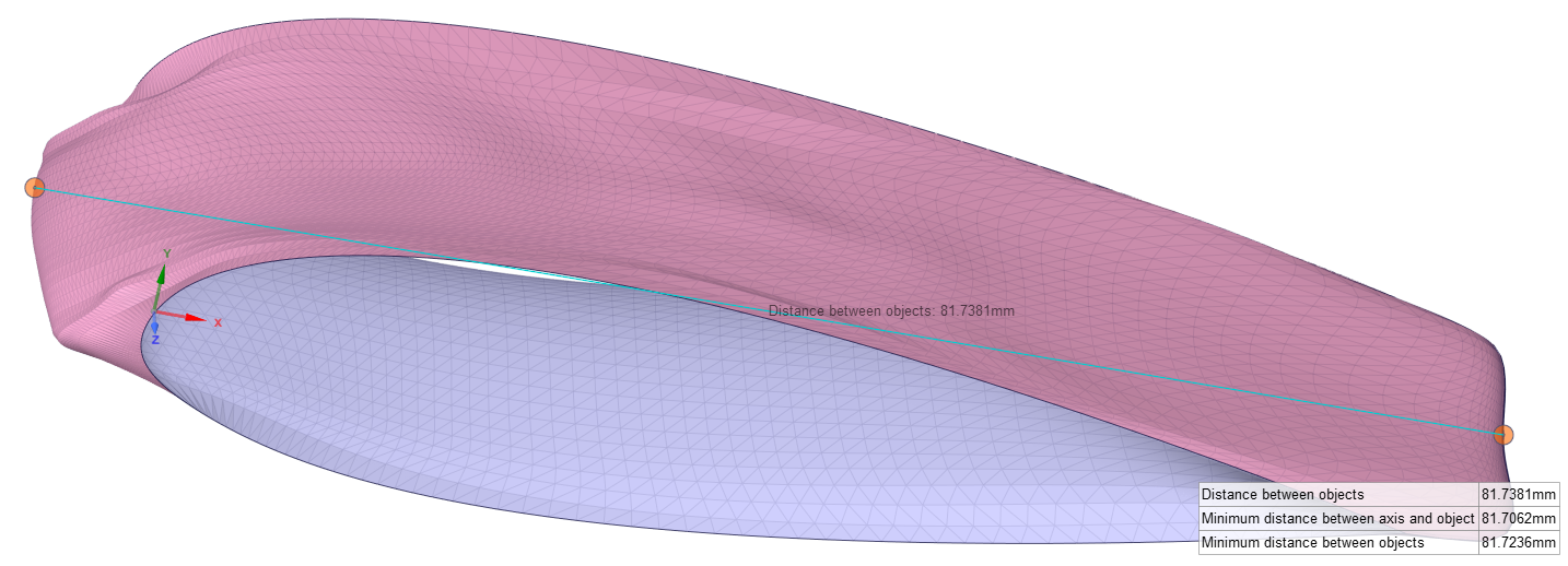
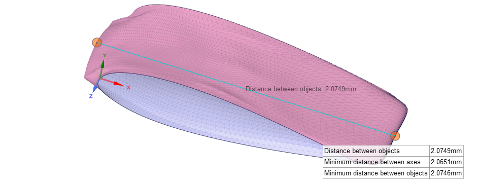
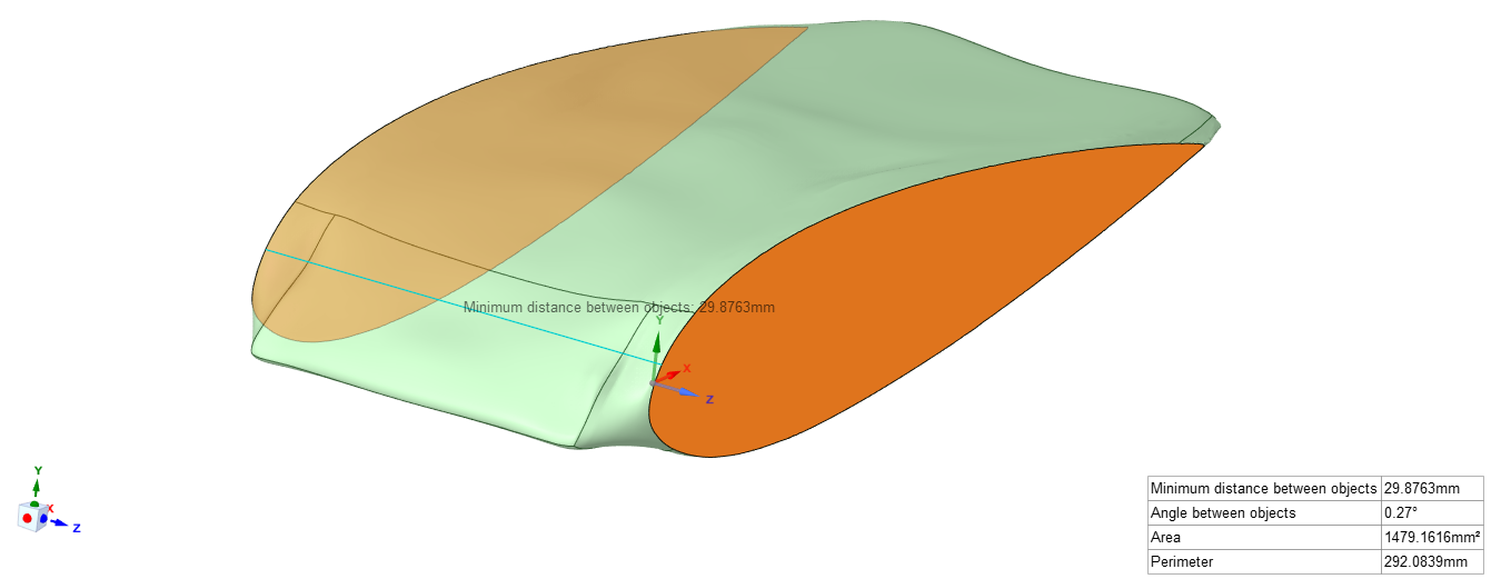
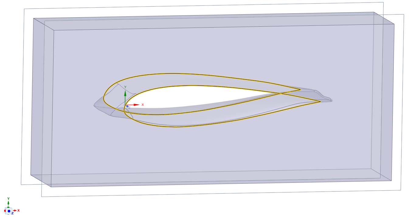
SubscriberThe reason for the lack of a clean interface at the ends of the wing is because the two planes are not aligned to the block of air. If you measure the two planes, they are not parallel. This was because the two edges of the STL file were not perfect planes.
This is easily repaired by creating two new planes from the Z axis and placing them slightly inside the solid body so a clean cut can be made.
Now in SpaceClaim, on the Prepare tab, an Enclosure can be created with 0 mm on each side. The edges are now very clean.
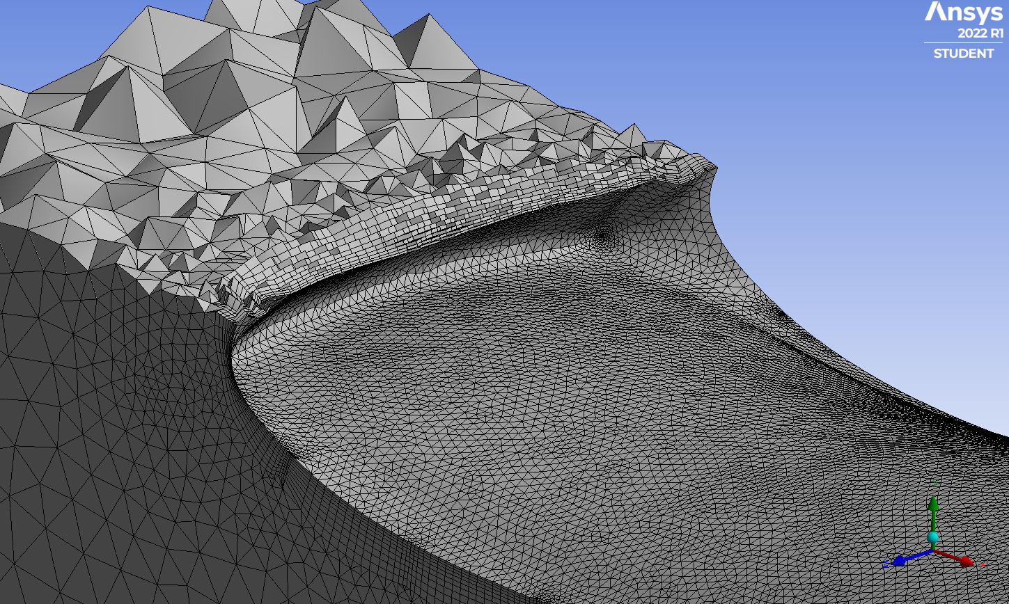
Even though there are many surfaces around the wing, this was meshed with only a few minutes setting up some simple mesh controls.
Improvements can be made if more time is spent on meshing.
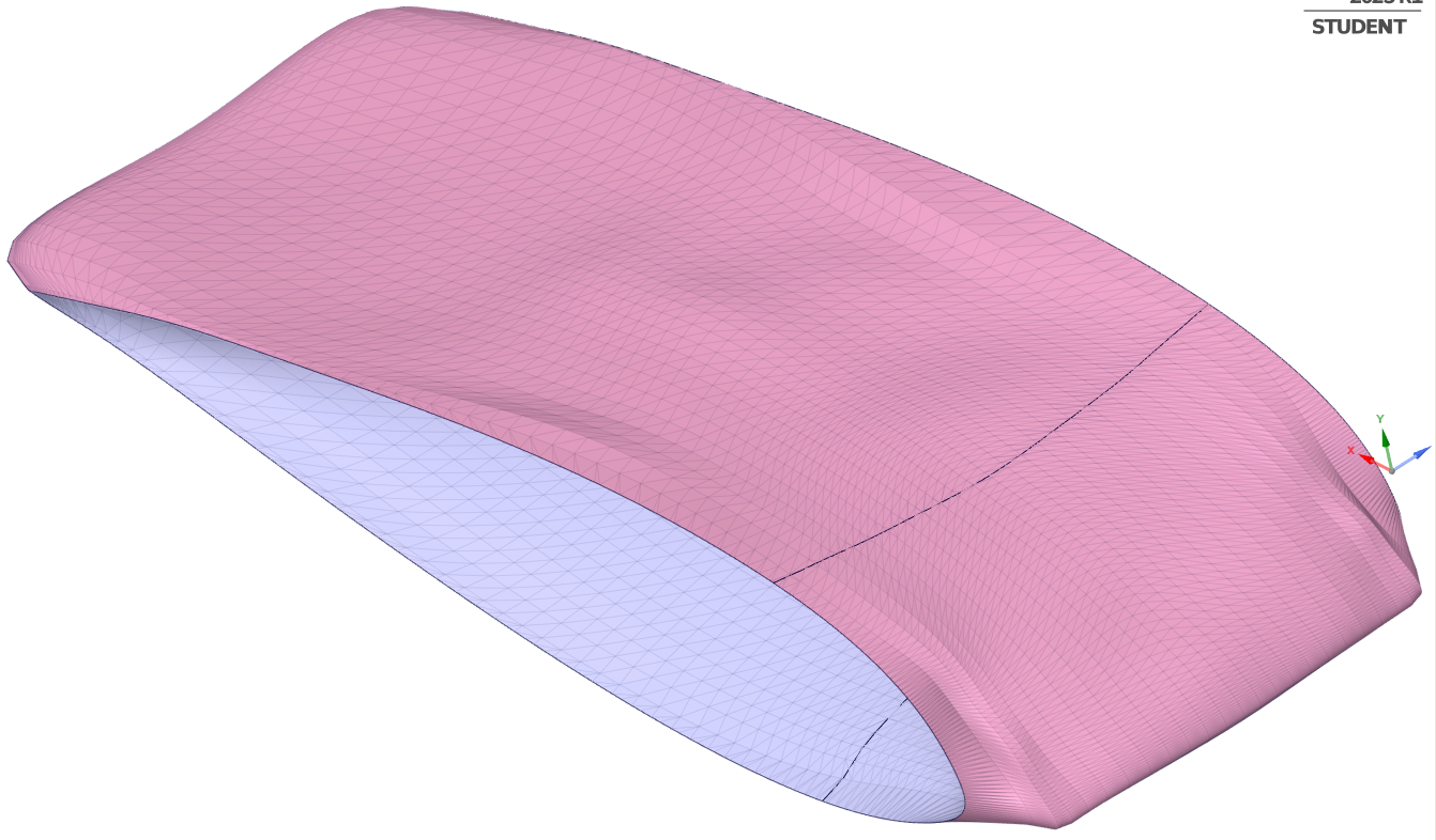
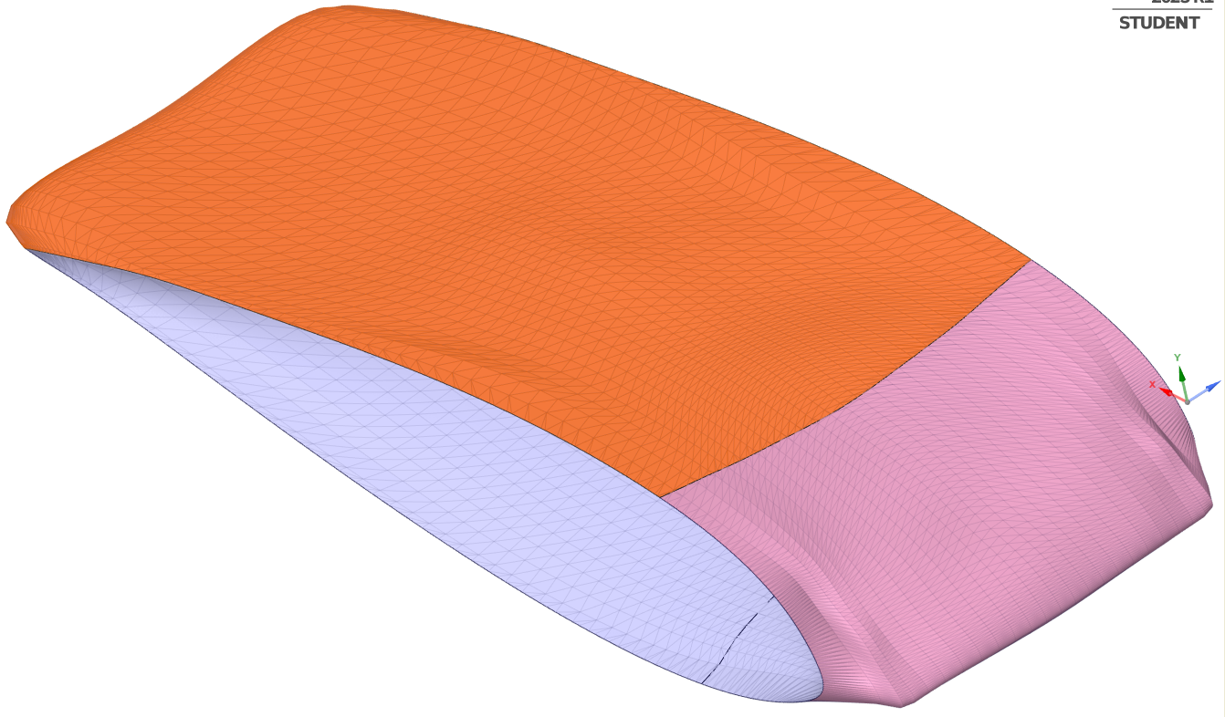
The image with no edges is just the same surfaces with the edges turned off.
-
April 6, 2023 at 10:18 am
Aras karimi
SubscriberThe distance between the two wing planes should be 30 mm. Are the two wing planes of the STL file parallel to each other and the distance between them is 30 mm, and after turning into a solid geometry, they are out of parallel and the distance between them is 30 mm Will it be less ?
What does it mean that (“the two edges of the STL file were not perfect planes”) ?
How can I create two new planes along the z-axis and place them inside the solid body ?
For meshing with wing Structure in ICEM software, as you know, this software works based on the lines in the geometry.Therefore, the large number of lines that are the border between fragmented surfaces creates a problem for blocking, so these lines must somehow not exist between fragmented surfaces.figure below:
What way do you suggest to solve this problem ?
If I turn off the display of edges in SpaceClaim, are there still fragmented surfaces in Design Modeler software? How to disable the display of edges in SpaceClaim ?
-
April 6, 2023 at 10:40 pm
peteroznewman
SubscriberHere is a plane made perpendicular to the Z axis at the origin. Notice the gaps between the edge of the STL and the plane. The plane has to move in the -Z direction toward the opposite side of the wing.
Here is a plane at exactly z = -30 mm and you can see there are gaps between the plane and the edge of the STL file.
So you can see the STL file cannot have parallel planes 30 mm apart without extending the surfaces to those planes. I suggest each plane be moved inward by 0.5 mm and cut the surfaces at that plane.
I don't use ICEM to mesh the air domain, I use Ansys Meshing, there is also Fluent Meshing. ICEM is probably not a good choice with an organic shape like this.
Turning off the visibility of edges does not change the surfaces at all, they are still there.
-
April 13, 2023 at 4:45 pm
Aras karimi
SubscriberHi Dear Peteroznewman,
I apologize for the delay in replying.Thank you very much for your guidance. I noticed that the two planes are not parallel and I have to cut the two sides of the shape a little.
But I still haven’t figured out how to convert the geometry STL file into a Solid wing with a Filled inside. I will be grateful if you teach me the process of doing this in the form of an educational video.Regards.
-
April 14, 2023 at 9:51 am
Aras karimi
SubscriberHi Dear Peteroznewman,
We are here to help each other to solve some of the problems of friends. Indeed, helping others is very valuable.
I spent a long time on my problem, which is converting the geometry STL file into a Solid wing with a Filled inside in SpaceClaim, and I could not do it successfully.
Please teach me how to do it in the form of a video.Just a humble request.Thanks in advance.
Regards.
-
-
April 12, 2023 at 12:39 pm
Aras karimi
SubscriberHello Dear Peteroznewman,
I apologize for the delay in replying.Thank you very much for your guidance. I noticed that the two planes are not parallel and I have to cut the two sides of the shape a little.
But I still haven’t figured out how to convert the geometry STL file into a Solid wing with a Filled inside. I will be grateful if you teach me the process of doing this in the form of an educational video.Regards.
-
April 14, 2023 at 11:48 am
peteroznewman
SubscriberThe audio quality is very poor on this video, which I recorded on April 1. Windows 10 is not recognizing any microphone that I plug in. I wanted to fix the computer and record a fresh video, but I haven't been able to fix the computer yet.
https://youtu.be/MDBLYG-9RO8
-
April 16, 2023 at 12:24 am
Aras karimi
SubscriberHello Sir Peteroznewman,
I sent you a message in the following post. I will thank you if you see it. I have been struggling with this problem for a long time and I have lost a lot of time. I am very confused and disappointed. If you help me, you have done me a great favor.
Thank you very much.
If you want to avoid long discussion, we can communicate via email.
Regards.
-
-
April 15, 2023 at 9:39 am
Aras karimi
SubscriberThank you very much for the video. I tried to convert another wing geometry from STL file to solid geometry exactly like you did in the video, but a lot of red lines appear at the end of the wing and it gives an error and it doesn’t convert to solid geometry. I did the following steps:
1) First, I created two Plane in the wing sections and closed both sides of the wing using the Holes option.
2) I clicked on Autoskin and the following image was obtained:
3) Next, I used the regularize and smooth options and finally clicked on Check Fast and received the following message:
(I chose the Regularize and Smooth values exactly like the values you chose in the video.)
4) I clicked on Autoskin twice, and the following figure was obtained and it gave an error:
I tried to do it exactly like you did but it didn’t work. What do you think is the reason for this error? Does every geometry have a special method to become a solid geometry? I have many geometries, how can I convert them into solid geometry without problems?
Regards.
-
April 17, 2023 at 12:51 am
peteroznewman
SubscriberAras,
Manipulating STL data in SpaceClaim is somewhat of a work of art. I have spent years developing a basic level of skill. With your wing data, if a sharp trailing edge was important, I would not use the smoothing method and the Autoskin tool because that leaves you with a rounded trailing edge. Is that acceptable?
Another approach, which is even more work than Autoskin, is to separate the leading edge, the top tail surface and the bottom tail surface. I started on that with the first wing. It has the possibility of having geometry with a sharp trailing edge.
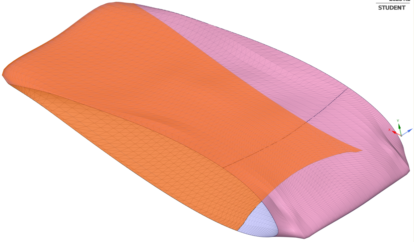 You can provide a link to a zip file of the STL of your second wing and I will have a look.
If you delete the trailing edge of your second wing, you can fill that in and smooth that out if you don’t care about a sharp trailing edge.
There is also the possibility of importing the STL into Fluent Meshing. I haven’t spent much time trying that out, but it might be worth investigating since it can operate on STL files directly. I expect you would have to have a closed STL body for the wing and subtract that from an STL of the air domain.
-
April 17, 2023 at 3:10 pm
Aras karimi
SubscriberHi Dear Peteroznewman,
I am glad that you answered me.Unfortunately, I have never used the Spaceclaim software and it is a matter of pride that I am learning something in your presence.
I would like the generated solid geometry to be exactly the same as the geometry in the STL file and not have the trailing edge rounded.The trailing edge of the first solid wing is also rounded and I want it to be sharp like the STL.I want to turn the second wing into a solid geometry exactly like its STL, which means it has a sharp trailing edge.
I don't think I can use Fluent Machining due to the blocking of wing geometry for meshing.
If you please teach me how to convert the STL of the first wing into a solid geometry so that it becomes exactly like its STL and its trailing edge is not rounded, I would be grateful.I will run it once on the second wing and if I am not successful, I will send you its STL file.
Thankyou very much.
Regards.
-
-
April 17, 2023 at 5:28 pm
peteroznewman
SubscriberFluent meshing is the next program to try. I don’t know what you mean by blocking. The video I saw made it look straightforward. I would take the STL wing, make two planes to square up the ends by cutting off a 0.5 mm layer, fill the holes and you will have a solid Facet Body. In Design, create a rectangular block between the planes for the air. Convert that solid to a Facet Body, then in the Facet tab, subtract the wing facet body from the air facet body. This is the STL file that you can import into Fluent Meshing water-tight meshing.
This is a workflow that will maintain the sharp trailing edge and use the exact STL facets. You might need to regularize the STL file to make higher quality elements.
Please start a New Discussion on the Preprocessing channel to get help using Fluent Meshing on an STL input file.
-
April 17, 2023 at 9:18 pm
Aras karimi
SubscriberWhat I mean by blocking is that in order to create an Strutured mesh, the air domain and the wing must be divided or blocked, and the ICEM software does this and finally creates an Strutured mesh.I use this software for Meshing.
I don't think Fluent Meshing will block and Structure the mesh.
I want the STL file of the wing to be converted into a solid wing with a Filled inside, taking into account its exact shape and without rounding its edges, including trailing edge.Then I take it to the Design modeler, draw the air domain there and subtract the wing from it And finally, I refer to ICEM software for Meshing.
Is it possible to convert the STL file of the wing without rounding its edges like the trailing edge, exactly like the STL geometry into a solid wing with a filled inside ?
(Purpose: The produced solid wing is exactly like the STL wing.)
-
-
April 17, 2023 at 10:21 pm
peteroznewman
SubscriberI'm suggesting you use an unstructured mesh. The benefit is that it's easily made to follow the STL surface. Boundary layers are easily made on the wing surfaces, so you don't lose accuracy from that. I understand that there will be more elements in an unstructured mesh than a structured mesh. That means the solver will run for longer and maybe a computer with more resources is required. But the time to make the mesh for each new wing shape will be much less than making a structured mesh on a solid model.
A huge amount of time will be spent making a solid model of each wing from the STL data and approximations to the shape will be introduced in the process. I don't think the benefits of a structured mesh can justify all the time spent making one for each new wing shape.
-
April 17, 2023 at 11:26 pm
Aras karimi
SubscriberYes, what you said is absolutely correct. I previously gridded a geometry using structured and unstructured grids and compared them to each other. As a result, due to the high number of elements produced in the unstructured mode, the solution time is extremely high, and the convergence residuals of the solution did not converge well compared to the structured mesh.The existing wing geometry is a three-dimensional geometry, and if an unstructured mesh is used, the number of its elements increases greatly, which increases the time of solving and is exhausting.Therefore, I think that using a structured mesh can help a lot in saving solving time.
I hope that it is possible to convert the STL wing to a solid wing with a filled inside so that it looks exactly like the STL wing. Is this possible and I look forward to learning how to do it.
By doing this, is it possible to ensure that all types of geometries with different shapes can be converted from STL to solid geometry that are exactly like STL ?
-
April 19, 2023 at 9:38 am
Aras karimi
SubscriberHi Dear Peteroznewman,
I am desperately waiting for your help, but I still haven't received a message. Did you manage to see my last message (above message)?
I have lost a lot of time for the problem of converting the STL to solid and I am very worried about the remaining works. If you help me, you have done me a great favor. I humbly request you.
Regards.
-
April 20, 2023 at 9:53 pm
Aras karimi
SubscriberHi Dear Peteroznewman,
In previous messages, you described an approach based on separating the leading edge, upper and lower surface of the wing, which can be used to achieve a solid geometry that is exactly like STL. How can I learn this method ?
Regards.
-
-
April 21, 2023 at 6:15 pm
peteroznewman
SubscriberHere is a video that shows some of the techniques you will use to create a structured mesh.
https://youtu.be/gINAySBv4zY
-
April 21, 2023 at 10:57 pm
Aras karimi
SubscriberHello and respect,
Thank you for sending the video. Dear Peter, my goal is that, like the first video, the STL wing will be converted into a solid wing with a Filled inside, with the difference that the surfaces and sharp edges are exactly like the STL. Is it possible ?
Because I want to take it to Design Modeler and draw the air domain and subtract the solid wing from it. I think that the second method (video 2) cannot be applied to geometries with different shapes, and the first method (video 1) will be more comprehensive.
I can also provide an STL file that includes the wing and the domain around the wing. Is this helpful?
-
-
April 21, 2023 at 9:19 pm
peteroznewman
SubscriberHere is a video that shows going straight from STL to Fluent Meshing.
https://youtu.be/e77SYdptbYE
-
April 22, 2023 at 11:16 pm
peteroznewman
SubscriberAras, you said, “I think that the second method (video 2) cannot be applied to geometries with different shapes“. That is not true. The Fluent Meshing approach is the easiest method to apply to different shapes. There are minimal operations to the original wing STL data. Each wing would be subtracted from the same air block in SpaceClaim on the Facet tab using the subtract tool. This is the method that keeps the resulting mesh closest to the original STL and takes the least amount of time.
The SpaceClaim Autoskin tool requires smoothing of the trailing edge, so that results in a significant deviation from the original STL, however a mesh can be created in a similar amount of time to the Fluent Meshing approach.
You say you prefer the SpaceClaim Skin Tool. You keep asking if geometry can exactly match the STL. Pay attention to the video at time 7:50 where I show that this surface is not exact. This video was made to show you some tools you can use, but it is by no means the complete solution to creating geometry that you can mesh. Three difficult areas are unexplored.
The first difficulty is matching surfaces at the boundary between one 10 mm block and the adjactent 10 mm block. Planes slice up the STL facets so the facets match exactly at the plane. One skin surface is created that approximately follows the facet edge on one side and another skin surface is created that approximatly follows the same facet edge on the other side, but unless you picked the exact same points for each surface, the spline curve will not be exact. I think that by the time you mesh the solid blocks of air, a Mesh Merge operation will allow nodes on each side that are very close to be merged into a single node, so this difficulty can be overcome fairly easily.
The second difficulty is slicing up the leading edge of the wing which I called the front in the video. This may require the solid body to be cylindrical or elliptical instead of a rectangluar block so it can approximately follow the normal vector from the STL. Perhaps this cylindrical or elliptical block of air can be merged with larger blocks of air to make the inlet boundary.
The third difficulty is slicing the block of air behind the trailing edge. This will require extending the trailing edge to create a cutting surface for the air. Maybe you can simply pull the rear edge of the surface. I don’t know.
In summary, slicing up the air into blocks and using the Skin tool is going to be a very time consuming exercise and will be a different challenge for each new wing shape. Contrast that to the Fluent Meshing approach that takes very little time and is the same few steps for each new wing shape.
Good luck in your meshing and simulation project.
-
May 4, 2023 at 8:58 am
Aras karimi
SubscriberHello and respect dear Peter,
I hope you are well, A problem happened to me and I could not appreciate you. I think you did not understand what I meant. I meant the first video (SpaceClaim AutoSkin), the second video (SpaceClaim SkinTool), the third video (Fluent Meshing approach). I said that the second video (skin tool) cannot be easily applied to all different shapes because it requires cutting facets of the STL geometry and has twists and deviations from the original STL geometry, and I said that the first video (i.e. Autoskin) It is more comprehensive
Because it easily and quickly converts STL geometry to solid, but unfortunately, the edges of the geometry are rounded after converting to solid. My question to you was whether there is a method like the first method (autoskin) that can quickly and easily turn the STL geometry into a solid with accurate preservation of its edges, without the need to cut the facets of the STL anymore?
I fully agree that the third method (Fluent Machining approach) can be applied to all geometries of different shapes, but I need to use the Structure mesh for the wing.
In the end, I have no choice but to use the same method (SpaceClaim Skin Tool). In this method, do I have to cut the facets of the STL and then use the skin surface tool to point around the cut facets and turn them into surfaces? Finally, should I connect the pieces of the created surfaces to each other and turn them into a solid Filled?
You said there are 3 problems in using this method. For the second problem, it is possible to use a circular domain for the leading edge of the wing. I did not understand the first and third problems. Can you explain it more clearly to me ?
-
-
May 5, 2023 at 12:41 pm
peteroznewman
SubscriberYes, you can use a circular domain for the leading edge.
For the first difficulty, complete the task I demonstrated in the video cutting the STL into 10 mm blocks and make a skin on the first square. Then do the adjacent square. Look at the edge of each square where they meet. Each square will have a slightly different edge if you picked different points along that edge when you were making each square.
The third difficulty is on the trailing edge. Say the last row of 10 mm cubes has about 5 mm of wing surface in the front of the cube and no wing surface in the back of the 10 mm cube. How are you going to cut the cube? You need to add a surface behind the trailing edge to the back of the domain to split the air into upper surface air and lower surface air. Maybe you can use the Blend tool to create that surface.
-
May 5, 2023 at 9:38 pm
Aras karimi
SubscriberYes, I understood the first problem and did it and saw that the edges of the two adjacent squares do not coincide with each other, which is like the figure below:What should I do to solve this problem?Unfortunately, I still didn't understand the third problem. I haven't drawn the air domain around the wing and I'm just working on the STL wing itself. In other words, I plan to create a surface on the STL facets which is divided into small squares of 10 x 10 mm, and after it is completed, like a puzzle, I will glue the created surfaces together and turn it into a solid filled and take it to Design Modeler to draw the air domain, but as if there is a gap between the levels. Is this work possible or must it be drawn directly air domain in the spaceclaim? Which one do you suggest?Other than posting the file here, is there any way I can send you the stl file of the second wing for you to take a look at? The second wing is more practical for me and may not have the third problem unlike the first wing.
-
-
May 6, 2023 at 12:28 am
peteroznewman
SubscriberSENDING FILES
The way you sent the first STL file worked. Use 7-Zip or Winzip to compress the STL file into a .zip file. Put that on your Google Drive and reply with the link. That is a good way to send me the STL file. Do you need another way?MATCHING EDGES
The image you show has only one piece of geometry and next to it is the facet body. Put the skin on that facet body and then look at the two edges of the two geometry squares with the facets turned off. The facet edges are identical for the two surfaces. If you click the same points for each surface, that will result in smaller deviations on the mating edges of the spline fit geometry.YOUR PLAN versus MY PLAN
The structured mesh video describes my plan, which is to create a block of air and slice it off at the wing surface. Each block of air above the wing or below the wing can be hex meshed. My plan directly meshes blocks of air and at no time is a filled solid of the wing created. You have a different plan which is to create a filled solid body of the wing. I don’t like your plan because it does not address how to mesh the air, which is the end goal.TRAILING EDGE
You may have trouble understanding the difficulty of meshing the block of air that contains the trailing edge becuase you are not thinking about the air, you are thinking about the wing. Follow my plan and put a plane 5 mm before the trailing edge and another plane that is 5 mm past the trailing edge. Cut out that block of air. There will be a wedge shaped piece of trailing edge cutout of that block of air, but you have to extend the sharp edge of that wedge from the middle of the block to the back side so you can end up with a hex meshable top block of air and bottom block of air. You need to create the surface that is the orange line in the illustration below to split the block into two pieces. Recall that the trailing edge is not a single straight line, but a lot of short lines which makes the task more difficult.-
May 6, 2023 at 4:07 pm
Aras karimi
SubscriberI want to send you the second STL file privately. How can I do this?YOUR PLAN versus MY PLANYes, it's true that your plan directly meshes the air blocks that are located above and below the wing. But in my plan, I do the blocking process in ICEM, so I need a solid wing to take it to Design Modeler and draw the air domain around the wing and finally subtract the filled solid wing from the air domain. Then I go to ICEM to create the air block and mesh the air domain.Air blocking process is a bit complicated, so I use ICEM for that.Is it possible for the STL wing to become a filled solid wing after reverse engineering ?TRAILING EDGEI found out the third problem, so that we don't face this problem, I divided the wing into three equal parts in direction span and the chord into seven equal parts. Therefore, the blocks of the last row on the surface of the wing (near the trailing edge) end at the trailing edge, and the air block that is located above and below the wing and includes the trailing edge can easily be separated from each other. which is according to the following figure:
-
-
May 6, 2023 at 5:13 pm
peteroznewman
SubscriberI don't need to see the second STL.
Yes, you can use the skin method to cut a wing from a solid block instead of cutting air from a solid block.
If you are cutting the wing, there is no difficulty at the trailing edge. Since I don't use ICEM, I don't know if that will be difficult or easy.
Good luck.
-
May 6, 2023 at 7:52 pm
Aras karimi
SubscriberDear Peter, I apologize for sending the message again.
It is good to reach a final conclusion after the final selection of the SpaceClaim SkinTool method from among the methods (SpaceClaim AutoSkin, SpaceClaim SkinTool and the Fluent Meshing approach) and to be able to create an STL geometry without blocking and grid problems. In SpaceClaim I just divided these blocks around the wing to show that there is no problem with the TE as shown above. I don’t know and I don’t understand how many methods I can use for structural meshing of the wing.
I do not understand the methods (cutting the wing from the solid block and cutting the air from the solid block). Here’s what I did: After opening the geometry STL file in SpaceClaim without drawing the domain or doing anything else, Using the SkinSurface tool, I drew irregular polygons on the facets of the STL geometry to create surfaces that looked like this:
By doing this, the shape of the wing is almost obtained from its STL, but I don't know how accurate it is.
I mean the photo on the right that after all its parts are completed, all the pieces of the surface are merged together and then it turns into a filled solid. Is this possible and correct ?
-
-
May 6, 2023 at 8:17 pm
peteroznewman
SubscriberIn the Skin tool video, at t=9:30 I use Split Solid to cut the block using a skin on the top surface. The top piece of the block is air, the bottom piece of the block is solid wing with more air below that. Once you skin the bottom surface of the wing, you will use that surface to split the bottom block. The bottom of that is air so the block between the air blocks is solid wing!
-
May 7, 2023 at 12:59 pm
Aras karimi
SubscriberI forgot to include the relevant photo in the above message, so I included the photo and updated its text.In the video (SkinTool), in fact, the air blocks that are located above and below the surface of the wing are meshed, and the solid inside the wing shell that is created is practically useless (Your PLAN). Am I right ?Now, is it possible to use the solid formed inside the wing shell for my PLAN? Or should another method be used to access the filled solid wing?
-
-
May 7, 2023 at 4:43 pm
peteroznewman
SubscriberYes, you understand my plan. The solid body inside the wing is deleted. Only the air is kept for meshing.
Your plan is to keep the solid body inside the wing and delete the air.
Having a watertight set of surfaces is one way to create a filled solid wing. You haven't shown how well an adjacent skin matches at the common edge between the patches. Once you cover the entire wing surface and the side openings in patches, it will automatically become a solid unless the edges don't match.
The other way to make a filled solid wing is to start with a solid block and cut the wing shape into it using Split Body, either keeping the air or the filled wing as I demonstrated in the skin tool video.
The size of the mismatches in the edges of adjacent skin patches should be smaller than the the smallest cell height of the air mesh on the skin. Have you already calculated the height of the first cell?
-
May 7, 2023 at 7:38 pm
Aras karimi
SubscriberTo create the surfaces, I did not cut the facets of the STL wing. I only drew irregular polygons on the wing with the skintool tool and converted them into surface. I sent a photo of it in the previous message.
(I drew a rectangle on the left side as an example)Yes, if I cut the facets of the STL into pieces and then created a surface on them, there was a possibility of a gap between the common edge of the side surfaces.
Does the second way to make a filled solid wing that you mentioned (skintool video) require cutting and slicing the facets of the STL wing?
I think YOUR PLAN requires cutting the STL facets into many parts. In other words, the more the STL wing is divided into many parts, the more the obtained geometry matches its STL. There is also the possibility of a gap between the common edge of adjacent surfaces.I am right ?
This creates an approximate shape of the wing and is not exact, and it would be great if there was a way to create a solid body without having to cut the facets of the STL wing in one piece. Is there any hope ?
-
-
May 8, 2023 at 1:29 am
peteroznewman
SubscriberCall this the “No Cuts” method.
Using planes to cut the STL surface is not required, but it is convenient to divide the task into managable pieces.
The tail section is the most difficult part of surfacing this STL.
https://youtu.be/k5J260NepRs
-
May 8, 2023 at 3:24 pm
Aras karimi
SubscriberIs this the next method and the only remaining method? In this method, how did you create 6 surfaces on the upper and lower surface of the wing? Did you cut the facets of the wing by creating three planes and then create a surface on the cut facets with the skin surface tool?
Unfortunately, the end part of the wing did not become the surface. What is the solution? In this video, what shape is the wing supposed to turn into at the end?
-
-
May 8, 2023 at 3:54 pm
peteroznewman
SubscriberSorry, I uploaded the wrong video, I’m changing the previous post. Refesh your browser page and watch the correct video and you will see I created the 6 surfaces using the Skin tool. I did not cut the STL file except for the two non-planar edges of the openings to make them planar as demonstrated in another video.
I ran into difficulty on the tail section and ran out of time to try again (and again), that was the video you just saw. It might work out for you. If not, I suggest you make one cut to separate the STL facets into three pieces: Leading Edge, Upper Tail and Lower Tail. In that way, the Skin tool will easily cover those three facet bodies.
In the end, you can use those three surfaces to split a solid block and end up with a solid wing. Good luck!
-
May 9, 2023 at 4:56 pm
Aras karimi
SubscriberI made a cut and divided the STL wing facets into three parts Leading Edge, Upper Tail and Lower Tail and covered the three faceted bodies using the skin tool. Now the two end edges of the upper and lower surface of the wing are not connected to each other, as if in some areas the upper surface is shorter than the lower surface and in some areas it is larger.All three photos are related to the Trailing edge of the wing. The middle photo shows that the upper surface is shorter than the lower surface, and the right photo shows that the upper surface is longer than the lower surface.( I will present the second wing.)
-
-
May 9, 2023 at 5:18 pm
peteroznewman
SubscriberI can't tell from the photos what is wrong.
-
May 9, 2023 at 6:06 pm
Aras karimi
SubscriberRight now, I am sending the second STL file here.
As soon as you download it, let me know so I can remove the link.no problem ?
-
-
May 9, 2023 at 10:37 pm
peteroznewman
SubscriberI'm online now if you want to reply with the link.
-
May 10, 2023 at 5:19 am
Aras karimi
SubscriberI have been waiting for you for a while but I have not received a reply. when are you online ?
-
-
May 10, 2023 at 11:17 am
peteroznewman
SubscriberI'm online now if you want to reply with the link.
-
May 10, 2023 at 12:02 pm
Aras karimi
SubscriberPlease let me know if you see it.
Thank you
-
-
May 10, 2023 at 12:13 pm
peteroznewman
SubscriberI've got it.
-
May 10, 2023 at 12:23 pm
Aras karimi
SubscriberHow do you rate it ?
Please, if you record a video of it, do not put it on YouTube and provide it to me through your Google Drive. Thankyou
-
-
May 10, 2023 at 5:32 pm
peteroznewman
SubscriberI can provide a link to a solid wing when you are available to download it.
-
May 10, 2023 at 5:50 pm
Aras karimi
SubscriberI am online now.
Was there a gap between the upper and lower Tail on the trailing edge of the wing ?
I would be grateful if you completely convert the second STL wing into a solid body from start to finish and give me its video.
-
-
May 10, 2023 at 5:59 pm
peteroznewman
SubscriberHere is the solid model and the facet body.
-
May 10, 2023 at 6:10 pm
Aras karimi
SubscriberI received the file.
-
May 10, 2023 at 6:15 pm
Aras karimi
SubscriberI received that. will you take it please ?
-
-
May 10, 2023 at 6:28 pm
peteroznewman
SubscriberRemoved link.
-
May 10, 2023 at 6:36 pm
Aras karimi
SubscriberThank you for removing the link.
When making the surfaces, was there no gap between the upper and lower tail at the Trailing edge ?
How did you overcome it ?
-
-
May 10, 2023 at 9:12 pm
peteroznewman
SubscriberOn the Design tab, I created a 0.5 mm thick block at the leading edge, then in Facets I subtracted that from the wing. I selected all the top facets and keyboarded Ctrl-C, Ctrl-V to create the top facet body and repeated that to create the bottom facet body. These bodies meet at the sharp straight edge of the trailing edge exactly. I used the Skin tool with lots of points along the side edges as I showed in my video to create a top surface. Repeat for the bottom surface. On the Design tab, I selected the two edges of the surfaces where the 0.5 mm gap was created in step 1 and used the Blend tool to fill in the gap. That gave a complete wing surface. I added two planes near the leading edge to cut the surfaces up for ease of meshing. I selected all the edges around the side opening and used the Blend tool to close each side. On the Repair tab, I used the Stitch tool to convert the surfaces into a solid body.
-
May 11, 2023 at 5:08 pm
Aras karimi
SubscriberI saw the file you sent for me. Apparently, there is no match between solid body and facet body in Trailing Edge. which is according to the following figure:
Unfortunately, I don’t understand your explanation about how to do it. Could you please send me the video of doing it in your Google Drive?
I took the solid wing that you sent for me to Design Modeler.There, I drew the air domain and tried to subtract the wing from air domain, but I encountered an error. This time, I drew the air domain in SpaceClaim and using the combine tool, I could not subtract the wing from the air domain.
-
-
May 11, 2023 at 11:04 pm
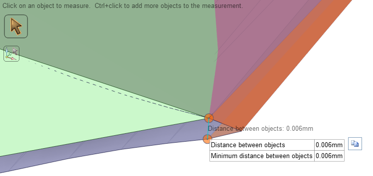
peteroznewman
SubscriberAras, your images have no length scale. Here, I measured it for you, it is 6 microns. Is that a significant dimension? What is the source of the STL file? Is the STL data computer generated from a model or is it scan data from a physical prototype? Even if the data is computer generated, when a physical prototype is made, I doubt it will be made to 6 micron tolerances.
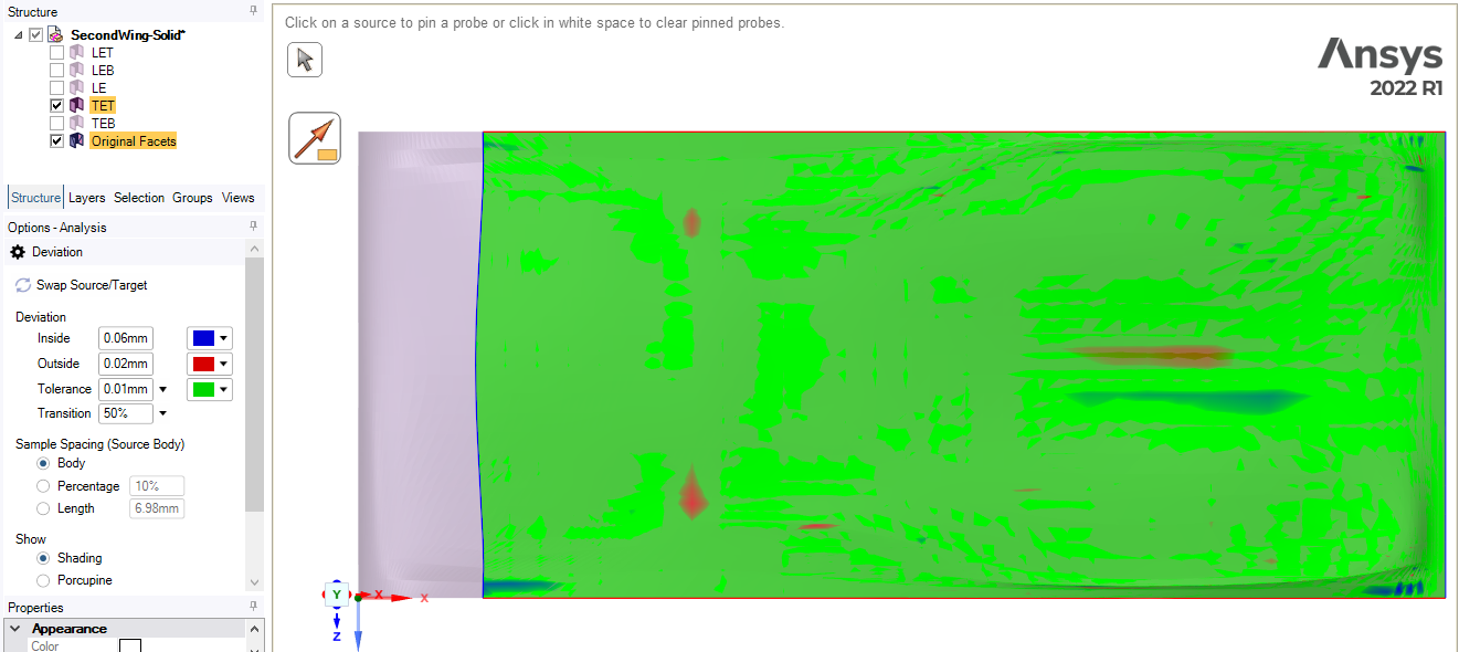
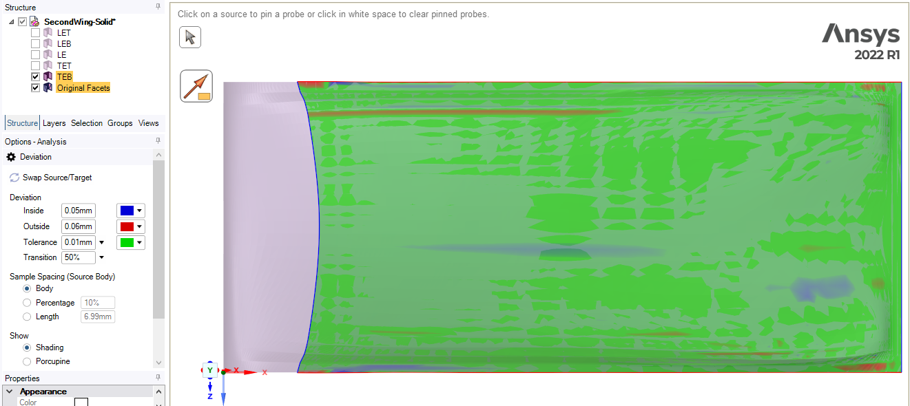
In my videos and my replies, I mentioned that the Skin tool is not exact, it does a best fit of a B-spline surface to the STL vertices and faces. I showed you how to use the Deviation plot in SpaceClaim so you can see the magnitude of the error. Here is a plot which shows the deviation between the STL facets and the top tail surface is +0.02 mm to -0.06 mm. This is a small fraction of the 70 mm chord length and these numbers are 10 times larger than the dimension you are showing above.
Here is the bottom surface deviation:
You need to decide what an acceptable tolerance is for deviation from the STL facet to the surface. Maybe while I was making the solid, I did not zoom in carefully to pick the exact last vertex on the STL. You can be more careful to not miss the last vertex at the trailing edge.
As I mentioned before, if you want zero deviation from the STL, then mesh the STL directly as shown in the Fluent video.
I did not record a video while making this solid.
Using SpaceClaim, I created two planes parallel to the XY plane. Move the first plane to Z = 0.1 mm and the second one to Z = 29.9 mm. Draw a block of air between those planes. Use the Combine tool to subtract the SolidFilledWing from the block of air.
I also tried a block of air that is wider than the wing and SpaceClaim had no problem subtracting the wing from the block of air.
-
May 12, 2023 at 4:16 pm
Aras karimi
SubscriberThe data is computer scanned and it is very good if the solid body and the facet body match each other as much as possible.
My acceptable tolerance is that the sharp edges on the STL wing are preserved as much as possible after being converted to a solid body. In other words, in the file you sent, the sharp ridges near the Trailing edge of the STL wing become almost round after turning into a solid body. Also, the sharp edges on the upper and lower surfaces of the STL wing are slightly rounded after turning into a solid body. Is there a way to increase the accuracy of the skin tool? Will increasing the number of samples from 50 to more values be useful and effective?
I drew the air domain completely tangent to the wing in the direction of thickness in Design Modeler and Spaceclaim. I encountered an error when subtracting the wing from the air domain. But when I drew the domain from both sides of the wing to a value of 0.1 smaller, I managed to subtract the wing from the air domain. Is it possible to subtract the wing without making the domain smaller on both sides?
I would be grateful if you could record a video of the ‘solid filled wing’ and send it to for me. (I would like you to record the steps of doing it from the beginning and step by step for me in this video, and if there is a method that increases the accuracy of matching surfaces with STL facets , please teach me , I would appreciate it)
-
-
May 12, 2023 at 5:24 pm
peteroznewman
SubscriberSo the STL data comes from a computer generated model. What is the name of the software that generated these surfaces? What is the data structure of the surface within that software? Is STL the only outuput format? What other output formats are available, for example Parasolid or STEP?
As much as possible is not a tolerance, you must specify a number for the acceptable deviation. That might be a tolerance on the normal distance between the surface and the facet as I showed above. If you want to maintain sharp edges, you can specify a tolerance on the angle between the normal vector of the surface and the normal vector on the facet. For example, an angle of 30 degrees would show a lot of rounding while an angle of 3 degrees would show a very small amount of rounding of the edges.
As I mentioned in the video, increasing the number of samples increases the accuracy that the surface will follow the facet body. A perfectly sharp edge requires that there be two surfaces. This is what I did when I separated the top and bottom surfaces and created a perfectly sharp trailing edge.
To avoid reducing the dimension of air along the wing span by 0.2 mm, try making the air wider than the wing span and subtract the solid body using the Combine tool. Use the Pull tool to move each end face of the cavity out by 0.1 mm then you can split the body at exactly Z=0 and Z=30 mm.
-
May 13, 2023 at 8:14 am
Aras karimi
SubscriberThe output format of the software is only STL and it does not output other formats.
To keep my sharp edges, how can I determine the angle between the surface normal vector and the facet normal vector ? How can I access the value of this angle ?
I didn’t understand the last paragraph you said about using the ‘Pull tool’ , it would be great if you could show me that in the next video you make.
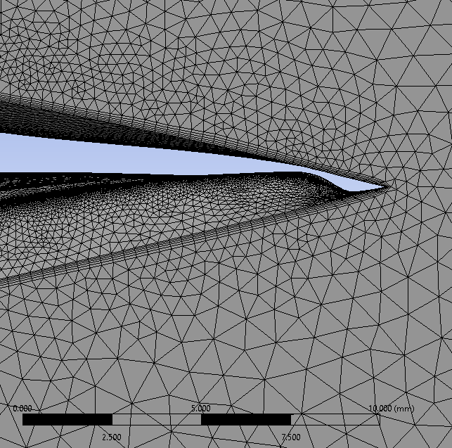
Peter, there is a problem. I meshed the solid wing file that you sent for me , but cells with negative volume are created on the wing, which the meshing software itself warns. which is according to the following figure:
I think the cause of this problem is the skin tool’s inability to create a surface on the upper tail. I tried this and observed that the control points of the skin tool near the trailing edge, on both sides, dip into the wing, as shown below:
Why do you think this problem occurs ?
Peter, before we come to a final conclusion, it would be nice to go through all the little points and problems that arise in the geometry, and finally, please send me a video.
-
-
May 13, 2023 at 11:50 am
peteroznewman
SubscriberThe problem you show in the last image is caused by fitting a skin surface to an area that has too much change in curvature. The solution is to skin smaller areas and have more faces in the surface.
I can’t comment on meshing problems with ICEM because I don’t use that software. When I use Ansys Mesh, there is no problem meshing the air around the solid filled wing.
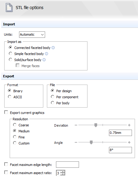
What output options are available to change the quality of the STL output from your unnamed softare? For example, here are the options for SpaceClaim. Notice in the Resolution section the controls over how closely the STL follows the underlying geometry that it is approximating with facets.
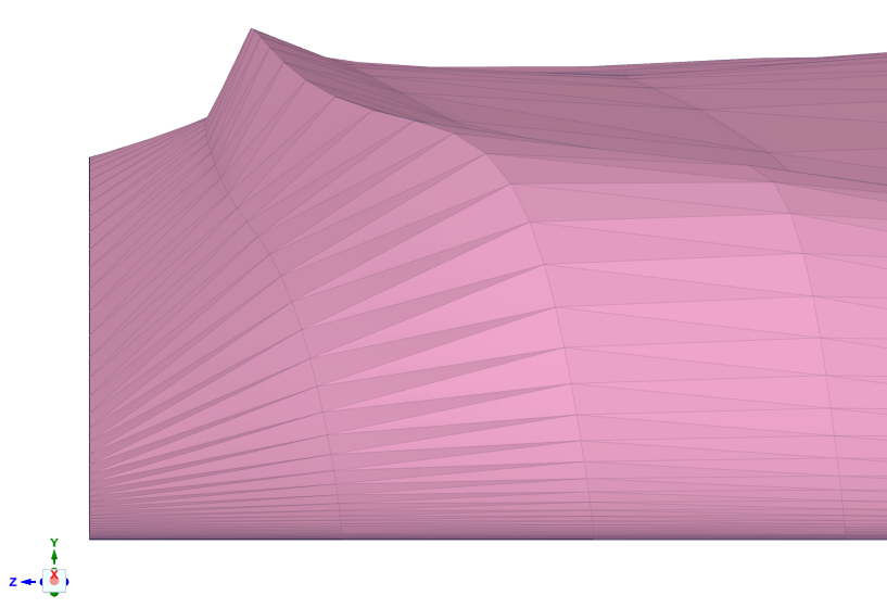
I found the sharp edges in the top side near the trailing edge. I see the sharp edge at the top of the peak, and a less sharp edge on the left just before the edge of the wing. Is that less sharp edge important or is it supposed to be smooth and you have an artifact in the STL representation of the real geometry in the unnamed software?
Here is a close up part of that peak:
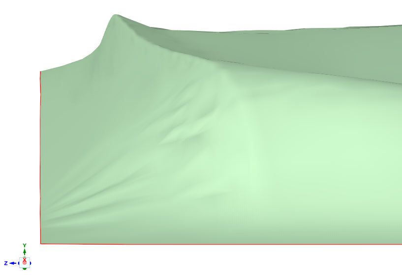
I made 3 faces using the Skin Surface tool. Notice that the top peak remains sharp, but the less sharp edge to the left of the peak has been smoothed, even though there is a face boundary.
Is that less sharp edge to the left of the peak important or is it supposed to be smooth and you have an artifact in the STL representation of the real geometry in the unnamed software?
-
May 13, 2023 at 5:19 pm
Aras karimi
SubscriberPeter, I will explain completely. are you online now ?
-
-
May 13, 2023 at 6:30 pm
peteroznewman
SubscriberI am online now.
-
May 13, 2023 at 6:43 pm
Aras karimi
SubscriberPlease let me know if you see the message.
-
-
May 13, 2023 at 6:48 pm
peteroznewman
SubscriberIf you have a Fluent mesh, why not use that mesh and not output the STL at all?
-
May 13, 2023 at 6:58 pm
Aras karimi
SubscriberThe wing is rigid and only the air flow is resolved. To access the deformed geometry mesh, only STL format is available.
-
-
May 13, 2023 at 7:10 pm
peteroznewman
SubscriberFluent solved on the deformed mesh. Are you saying you don't have access to that mesh?
-
May 13, 2023 at 7:24 pm
Aras karimi
SubscriberAt first, the geometry mesh file is available. After the geometry is deformed, the mesh file I can have is only and only STL form.
-
-
May 13, 2023 at 7:37 pm
peteroznewman
SubscriberThat is disappointing. It would be good to have the final mesh that was used to solve the flow.
-
May 13, 2023 at 8:50 pm
Aras karimi
SubscriberThe final mesh used to solve the flow is the STL file I sent for you. So what should we do?
Are there specialized software that STL geometry To make it solid by carefully maintaining its sharp edges?
-
-
May 13, 2023 at 10:21 pm
peteroznewman
SubscriberThe STL is not a CFD mesh, just a way to digitize a surface or volume. The CFD mesh consists of 3D elements in the shape of a tetrahedral, a hexadral, or wedge element. The mesh can be exported from a Fluent model. The exact shape of the air domain solved in Fluent is available to be solved again and the surface of the wing is represented exactly in that mesh.
Can you see the Fluent CFD mesh? I suspect that the size of the elements used to solve the Fluent model are smaller than the size of the facets of the STL file. Can you confirm that? If what I suspect is true, the STL file may have significant errors in the geometry compared to the mesh used by Fluent. It is worth expending some effort to get that mesh.
-
May 14, 2023 at 12:37 pm
Aras karimi
SubscriberPeter are you online now?
-
-
May 14, 2023 at 2:23 pm
peteroznewman
SubscriberYes I am.
-
May 14, 2023 at 3:30 pm
Aras karimi
SubscriberPicture
-
-
May 14, 2023 at 3:34 pm
Aras karimi
SubscriberDid you see the message?
-
May 14, 2023 at 3:51 pm
Aras karimi
SubscriberI left a message, you were not online. When exactly are you online ?
-
May 14, 2023 at 4:01 pm
peteroznewman
SubscriberThat is a good comparison Aras, I agree that the STL file is fairly accurate representation of the Fluent mesh rigid surface of the wing. There is a small difference between a twisted quad element face and two triangular faces, but at least there is not a huge difference.
I am not expert at Fluent, but a fluent .msh file is just a stripped down .cas file.
Try the following to get the .msh file from .cas file:
1. In Fluent Solution Mode (normal mode), write a .cas file
2. Launch Fluent in the Meshing Mode by ticking “Meshing Mode” in the Fluent Launcher
3. Read the .cas file just saved by File>Read>Mesh… then it prompt “Reading a case file as a mesh file results in loss of boundary conditions.” Press OK.
4. Write the mesh as .msh by File>Write>Mesh…-
May 14, 2023 at 4:07 pm
Aras karimi
SubscriberIs my message still available or has it been deleted ?
-
-
May 14, 2023 at 5:28 pm
Aras karimi
SubscriberIs the above message that I compared the two photos available or has it been deleted?
Peter, I think there is no need to write the .case file because I have the .case file and the desired geometry. Only the .msh file should be extracted from it. I opened Fluent and then set it to meshing mode and imported the .cas file into Fluent. Next, I clicked on File -> Write -> Mesh and outputted the .msh file, but the output file is in '.msh.h5 ' format. Is this what you mean ? I opened this in Fluent with no problem.
-
May 14, 2023 at 5:46 pm
peteroznewman
SubscriberAras, the messages and photos were deleted while I was researching and writing my reply.
Yes, from the .cas file you can extract a .msh file that can be read into Fluent. The msh.h5 is a compressed format. Now you will be able to use the exact mesh that was used in previous simulations. Isn't that the best possible outcome?
-
May 14, 2023 at 6:16 pm
Aras karimi
SubscriberPeter, now we have two files: 1- The STL file that we have been discussing for some time.2- This is the mesh file that I just output and its format is '.msh.h5 ' What is the use of this file ? -
May 14, 2023 at 6:31 pm
peteroznewman
SubscriberYou confirmed that the STL file and the wing surface in the Fluent mesh have the same shape. You won’t use the STL file at all. The mesh file can be used to simulate airflow around the wing without the use of the STL file. In fact the .cas file is better because it has the fluid properties, inlet boundary conditions, outlet boundary conditions and the other boundary conditions at the other faces of the air domain, as well as the turbulence model etc. to allow you to do simulations in Fluent at other conditions.
-
May 15, 2023 at 10:24 am
Aras karimi
SubscriberPeter, I cannot use the same mesh to solve the next flow, so I must mesh the outputted geometry.
two files are available: one is the STL file meshing, and one is the outputted mesh whose format is .msh.h5.
Is it possible to convert the file mesh .msh.h5 to a solid filled geometry ?
-
-
May 15, 2023 at 10:30 am
peteroznewman
SubscriberI am online now if you want to send me a link to the .msh.h5 part. I will reply as soon as I have it.
-
May 15, 2023 at 12:48 pm
Aras karimi
SubscriberIs it possible to convert the file mesh .msh.h5 to a solid filled geometry ?
-
May 15, 2023 at 12:54 pm
peteroznewman
SubscriberI don’t know, but I am willing to do some research
like I did to find out how to get a .msh.h5 file from a .cas file.[Edited for clarity] -
May 15, 2023 at 1:05 pm
Aras karimi
SubscriberPeter, you are wrong.
I extracted the .msh.h5 file from the .case file. Now, do you intend to convert this .msh.h5 file into a solid body ?
-
May 15, 2023 at 1:08 pm
peteroznewman
SubscriberWhat exactly am I wrong about?
-
May 15, 2023 at 1:13 pm
Aras karimi
SubscriberYou say you want to research how to extract the .msh.h5 file from the case file. But I did it. Now, is it possible to convert the .msh.h5 file into a solid body ?
-
May 15, 2023 at 1:19 pm
peteroznewman
SubscriberYou misunderstood me. I told you how to extract the .msh.h5 file from the case file and you did it.
I was proposing research on how to convert the .msh.h5 file into a solid body.
-
May 15, 2023 at 1:30 pm
Aras karimi
SubscriberSo you typed wrong. You said that I have a research about converting the .msh.h5 file to the .cas file.
-
May 15, 2023 at 1:42 pm
peteroznewman
SubscriberYes, I could have been clearer about what I was proposing to research, but now I'm not that interested to find out about it.
-
-
-
May 15, 2023 at 11:30 am
peteroznewman
SubscriberI assume that this mesh is too coarse for the next flow you wish to simulate. Are there other changes in the mesh that are required besides a mesh refinement?
-
May 15, 2023 at 12:33 pm
peteroznewman
SubscriberThis discussion thread is over 100 replies long so I have requested that it be closed.
Please start a New Discussion if you have additional questions.
-
May 15, 2023 at 3:56 pm
is it open?
-
May 15, 2023 at 4:07 pm
peteroznewman
Subscriberapparently
-
May 18, 2023 at 8:27 am
Aras karimi
SubscriberHi peter,
Did you understand how to convert .msh.h5 file to solid body ?
-
May 18, 2023 at 12:32 pm
peteroznewman
SubscriberAras,
Sometimes I find interesting CFD models on the forum. Sometimes I find interesting STL data on the forum. Your thread was initially interesting. My interest has faded because of the secrecy you require. I enjoy helping people who appreciate the help I provide, but I'm not feeling it in this thread.
I suggest you start a New Discussion in the Fluids category.
Good luck,
Peter
-
May 18, 2023 at 1:21 pm
Aras karimi
SubscriberPeter, you judge wrongly.I have appreciated your valuable help several times and I will not repeat it again so that the messages of gratitude and thanks are not repetitive and boring.You are a very good and valuable person for me and I will never forget you. In this topic, our discussion is very good and technical and will help future researchers a lot. It would be great if we continue, please. Thankyou
-
- The topic ‘How to convert STL file to STEP geometry file in SpaceClaim’ is closed to new replies.


-
5159
-
1836
-
1387
-
1249
-
1021

© 2026 Copyright ANSYS, Inc. All rights reserved.


