TAGGED: -2d-materials-and-metals, #TFSF, 3DFDTD, metal, scattered-field, scattering
-
-
April 20, 2024 at 2:01 pm
10172100207
SubscriberWhy does Lumerical example(defect scattering) use the difference of two cone volume integrals to obtain the scattered power in the PSL.lsf script?
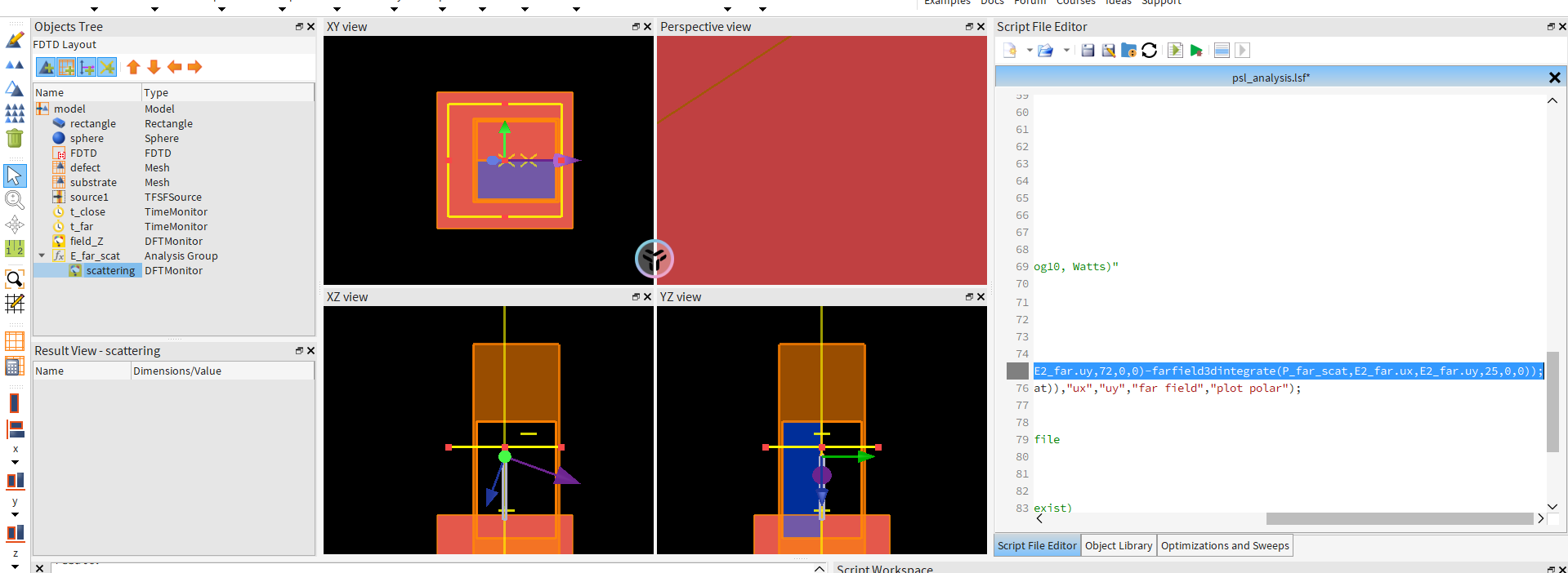
the model:
Here is the script:
############################################
# file: psl_analysis
# Description: This file is used to calculate
# the scattering from PSL spheres. It runs
# a reference simulation as well as the defect
# simulations.
# After the simulations are complete, the far
# fields are calculated. The reference far field
# is subtracted from the defect far field,
# giving the scattered far field.
#
# Copyright 2010 Lumerical Solutions Inc
############################################
polarization = "P"; #sets which polarization to run: "P", "S", "C" (circular)
run_simulations = 1; # set to 0 to analyze previously run simulations
if (run_simulations) {
switchtolayout;
if (polarization=="P") {
setnamed("FDTD","x",1e-6);
setnamed("source1","polarization angle",0);
setnamed("source1","angle theta",70);
setnamed("FDTD","y min bc","Symmetric");
select("source2");
delete;
}
if (polarization=="S") {
setnamed("FDTD","x",1e-6);
setnamed("source1","polarization angle",90);
setnamed("source1","angle theta",70);
setnamed("FDTD","y min bc","Anti-Symmetric");
select("source2");
delete;
}
if (polarization=="C") {
setnamed("FDTD","x",1e-6);
select("source2");
delete;
setnamed("source1","polarization angle",0);
setnamed("source1","angle theta",0);
setnamed("FDTD","x",0);
select("source1");
copy;
set("name","source2");
set("polarization angle",90);
set("phase",90);
setnamed("FDTD","y min bc","PML");
}
runsweep;
save;
}
swp="sweep_rad";
farfieldfilter(0.5);
# get the data from the sweep
E2_far=getsweepresult(swp,"E2_far");
T=getsweepresult(swp,"T");
SP=getsweepresult(swp,"SP");
rad = E2_far.rad;
res = length(E2_far.ux);
E2=E2_far.E2_far;
#plot(rad*1e9,log10(T.T*SP.SP),"radius (nm)","scattered power (log10, Watts)"
scat_power=matrix(length(rad)); #创建矩阵存储不同半径的scat_power
for (i=1:length(rad)) {
P_far_scat = sqrt(eps0/mu0) * pinch(E2(1:res,1:res,i));
scat_power(i) = 0.5*(farfield3dintegrate(P_far_scat,E2_far.ux,E2_far.uy,72,0,0)-farfield3dintegrate(P_far_scat,E2_far.ux,E2_far.uy,25,0,0));
image(E2_far.ux,E2_far.uy,pinch(P_far_scat)/pinch(max(P_far_scat)),"ux","uy","far field","plot polar");
}
savedata("psl_"+polarization,scat_power); # save data to an ldf file
# plot results from P,S,C polarization on same plot (if results exist)
if (fileexists("psl_p.ldf")) { loaddata("psl_P"); spP = scat_power; } else { spP = 0; }
if (fileexists("psl_s.ldf")) { loaddata("psl_S"); spS = scat_power; } else { spS = 0; }
if (fileexists("psl_c.ldf")) { loaddata("psl_C"); spC = scat_power; } else { spC = 0; }
if (spP==0 ) {spP=0*rad; }
if (spS==0 ) {spS=0*rad; }
if (spC==0 ) {spC=0*rad; }
plot(2*rad(1:length(rad))*1e9,log10(spP),log10(spS),log10(spC),"Diameter (nm)","log10(scattered power)");
legend("P","S","Circular");
My problem:
scat_power(i) = 0.5*(farfield3dintegrate(P_far_scat,E2_far.ux,E2_far.uy,72,0,0)-farfield3dintegrate(P_far_scat,E2_far.ux,E2_far.uy,25,0,0));
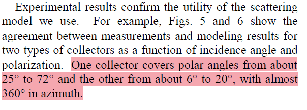
Why does it use the power with a half-angle of 72 degrees minus the power with a half-angle of 25 degrees? How are the values of 72 and 25 determined?
-
April 22, 2024 at 5:53 pm
-
- The topic ‘How to calculate scattering power?’ is closed to new replies.


-
4823
-
1587
-
1386
-
1242
-
1021

© 2026 Copyright ANSYS, Inc. All rights reserved.


