TAGGED: ansys-mechanical, boundary-conditions
-
-
August 5, 2021 at 5:19 am
TYUST10086
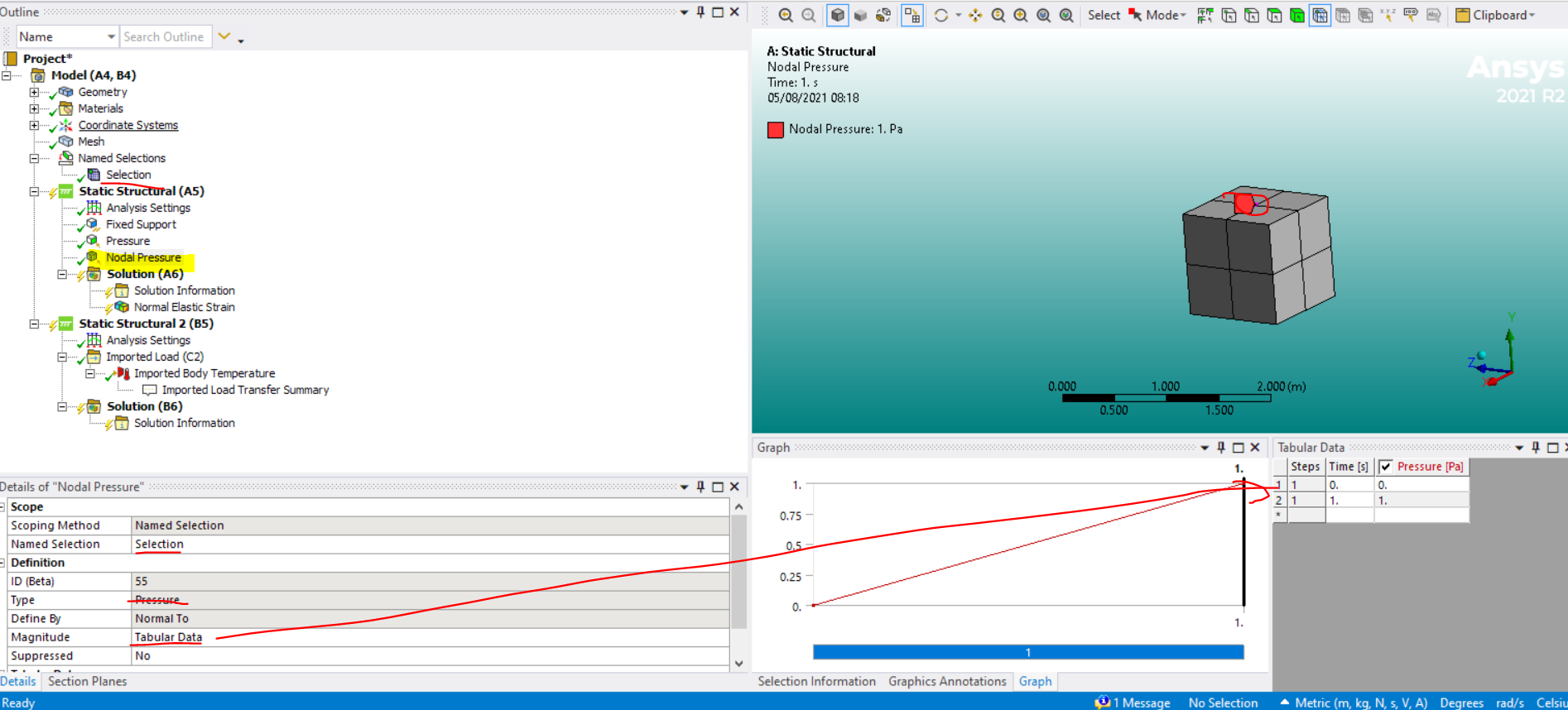
Subscriberthe pressure curve was given, and i want to apply this pressure data to the specific nodes, thank you.
August 5, 2021 at 7:19 amAugust 5, 2021 at 8:04 amTYUST10086
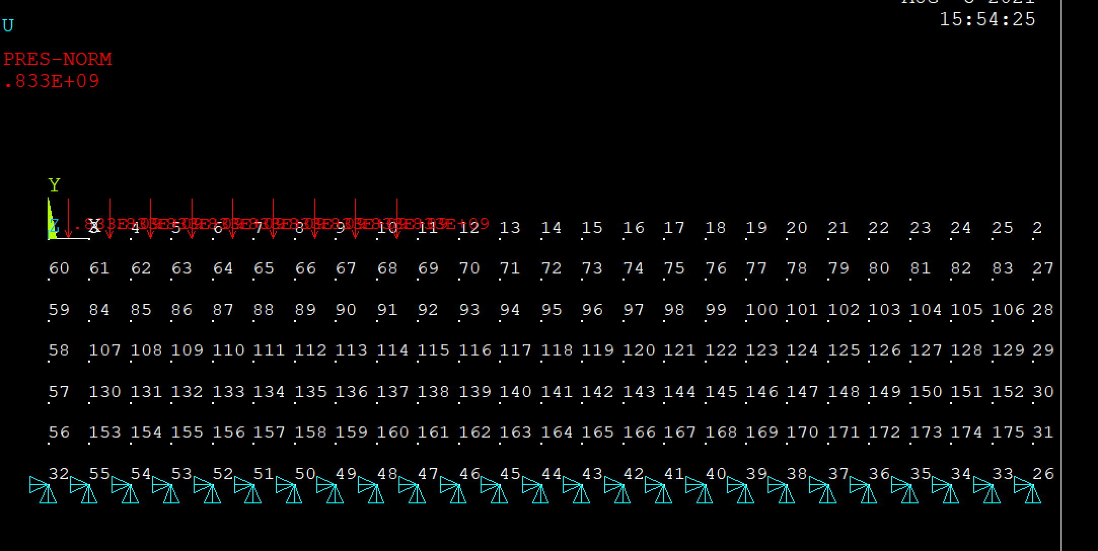
SubscriberThank you for your kind answers. the simulation was performed in ANSYS APDL experiment. as show below Fig.1
 Fig.1
Fig.1
the red arrows shows the pressure conditions and the results shows the applied pressure values are constant values, as shown in Fig.2
 Fig.2
Fig.2
while I applied the following command to apply the given pressure data (for simplification, I defined two points ) to the nodes: 1, 3,4,5,6,7,8,9,10,11
*DIM,eqps,TABLE,2,1,1
*TREAD,eqps,fps,TXT,,1
FLST,2,10,1,ORDE,3
FITEM,2,1
FITEM,2,3
FITEM,2,-11
SF,P51X,PRES, %EQPS%
 the results was wrong, as illustrated in Fig.2 . which should not be constant. thank you.
August 5, 2021 at 8:25 amErKo
Ansys EmployeeHI
It is just a visual thing - you can display a table.
Just look on the reactions (@fixed nodes) when it is solved in POST1/ and see that it is changing with time - make your table like 0 , 5E8, 0.5 s, 5E8 Pa, and 1.5 s1E9 Pa, and 2 say s 1.9E9.
The reaction should change for different time say @ 0.5 s compared to 2 s.
August 5, 2021 at 8:41 amTYUST10086
SubscriberAugust 5, 2021 at 8:48 amErKo
Ansys EmployeeHI
Ansys employees are not allowed to download files - perhaps other members can help you looking at the files (we can not)
I think you talk about variation along a dimension not time.
I am not sure if it works , but in the *dim table you need to tell it it is a position table by default it is a time table - see *dim for more info.
Thank you
Erik
August 5, 2021 at 8:54 amTYUST10086
Subscriberyes, you are right. I want to apply the variational pressures along the selected nodes dimension. as below
/PREP7
ET,1,PLANE182
!*
KEYOPT,1,1,0
KEYOPT,1,3,2
KEYOPT,1,6,0
!*
MPTEMP,,,,,,,,
MPTEMP,1,0
MPDATA,EX,1,,2e11
MPDATA,PRXY,1,,0.3
K,100,,,,
K,101,12,,,
K,101,12,-3,,
K,101,12,,,
K,102,12,-3,,
K,103,0,-3, FLST,2,4,3
FITEM,2,100
FITEM,2,101
FITEM,2,102
FITEM,2,103
A,P51X
TYPE,1
MAT,1
REAL,
ESYS,0
SECNUM,
!*
FLST,5,1,4,ORDE,1
FITEM,5,2
CM,_Y,LINE
LSEL, , , ,P51X
CM,_Y1,LINE
CMSEL,,_Y
!*
LESIZE,_Y1,1, , , , , , ,1
!*
FLST,5,1,4,ORDE,1
FITEM,5,1
CM,_Y,LINE
LSEL, , , ,P51X
CM,_Y1,LINE
CMSEL,,_Y
!*
LESIZE,_Y1,1, , , , , , ,1
!*
MSHAPE,0,2D
MSHKEY,1
!*
CM,_Y,AREA
ASEL, , , ,1
CM,_Y1,AREA
CHKMSH,'AREA'
CMSEL,S,_Y
!*
AMESH,_Y1
!*
CMDELE,_Y
CMDELE,_Y1
CMDELE,_Y2
!*
ESIZE,0.5,0 CM,_Y,AREA
ASEL, , , ,1
CM,_Y1,AREA
CHKMSH,'AREA'
CMSEL,S,_Y
!*
!*
ACLEAR,_Y1
AMESH,_Y1
!*
CMDELE,_Y
CMDELE,_Y1
CMDELE,_Y2
!*
FINISH
/SOL
FINISH
/PREP7
FINISH
/SOL
!*
ANTYPE,0
!*
!*
NLGEOM,0
NROPT,AUTO, ,
LUMPM,0
EQSLV, , ,0, ,DELE
MSAVE,0
PCGOPT,0, ,AUTO, , ,AUTO
PIVCHECK,0
PSTRESS,0
TOFFST,0,
!*
FLST,2,1,4,ORDE,1
FITEM,2,3
!*
/GO
DL,P51X, ,ALL,0
!
*DIM,eqps,TABLE,2,1,1
*TREAD,eqps,fps,TXT,,1
!
FLST,2,10,1,ORDE,3
FITEM,2,1
FITEM,2,3
FITEM,2,-11
/GO
!*
!*
SF,P51X,PRES, %EQPS%
OUTRES,ALL,ALL,
!*
TIME,1
AUTOTS,1
NSUBST,50,200,50,1
KBC,0
!*
TSRES,ERASE
LSWRITE,1,
SOLVE
August 5, 2021 at 9:21 amErKo
Ansys EmployeeSo you need to have a position table not time like you have now.
See the *dim command and the options there (time,x,y,z).
An example is below where the load varies along Z:
--
/PREP7
!*
ET,1,SOLID185
!*
!*
MPTEMP,,,,,,,,
MPTEMP,1,0
MPDATA,EX,1,,200E9
MPDATA,PRXY,1,,0.3
/REPLOT,RESIZE
BLOCK,0,1,0,1,0,1,
VMESH,ALL
*DIM,my_conv,table,3,1,1,Z! 3 rows, One Column, function of Z
!
! Zero out the ÔÇ£zerothÔÇØ row values for neatness
my_conv(0,1)=0.0
!
! Enter the Z locations
my_conv(1,0)=0! start loc
my_conv(2,0)= 0.5! 0.5 m
my_conv(3,0)= 1! 1 m
!
! Enter force
my_conv(1,1)=0
my_conv(2,1)=100.0
my_conv(3,1)=200.
NSEL,S,LOC,Y,0
sf,ALL,pres,%my_conv%
ALLSEL,ALL
NSEL,S,LOC,Y,1
d,all,all
OUTRES,ALL,ALL
/SOLU
solve
--
Viewing 7 reply threads- The topic ‘how to apply pressure boundary conditions to the nodes with table form.’ is closed to new replies.
Innovation SpaceTrending discussionsTop Contributors-
5094
-
1831
-
1387
-
1248
-
1021
Top Rated Tags© 2026 Copyright ANSYS, Inc. All rights reserved.
Ansys does not support the usage of unauthorized Ansys software. Please visit www.ansys.com to obtain an official distribution.
-


