General Mechanical

General Mechanical

Topics related to Mechanical Enterprise, Motion, Additive Print and more.

How to apply a vibration displacement only in a section of a structure?

    • Geovanna Quinde
      Subscriber

      Hello, I am modelling a section of a ship's structure and i want to see its response due to a displacement vibration but i do not want to apply it only to a point, cause it will produce a concentration of stresses near that point. I want to vibrate only a section and see the response of the entire structure. I am using Harmonic response module. 


      Can you @peteroznewman please answer this? ?

    • peteroznewman
      Subscriber

      Hello Geovanna,

      It will be helpful if you can put some images in your reply so I can see at what point you want to apply the displacement and the boundary conditions you are using to support the section of the ship.

      Regards,

      Peter

    • Geovanna Quinde
      Subscriber

      Hello Peter, thank you for your reply. This is the section the ship, this geometry is between two watertight bulkheads (bulkheads are not included) and two decks (decks not included). Because of symmetry we did just one side. 

      We try to simulate the vibration produced by onboard machinery and see the response of this vibration in the geometry. To include vibration, we thought we could include it as a displacement.

      1. Playing around with the program we realized that we can’t include a displacement when using the mode superposition method. Why is this happening?

        So we did a full harmonic solution method, and we saw that Displacement and Nodal Displacement can be applied. What is the difference between them?
      2. Then, we applied a Nodal Displacement of 2.5 mm, but we are not sure about what displacement we can enter, Do you have some references to see what amplitude of displacement is okay?
      3. For a full harmonic solution method, we include a constant structural damping coefficient, but while looking for some reference values we found a longitudinal loss factor, are they the same? Or we can just double the viscous damping ratio? 
      4. These are the boundary conditions for the geometry, we are going to consider to expand this geometry since applying fixed supports in the borders near the region of interest, will affect the asnwer. Do you have any recommendation for boundary conditions?
      5. We have seen that in harmonic module it is included some boundary conditions, are they for the whole geometry or for some sections where the vibration is located? 
      6. Finnally, the way we consider to simulate the source of vibration is the adecuate or it is better to consider a force? 


    • peteroznewman
      Subscriber

      Hello Geovanna, I will answer the questions and invite others with more expertise to also reply.

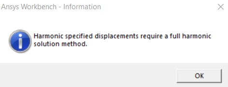
      1.       Different mathematical equations are used for MSUP analysis than Full Harmonic.  I can’t point to the specific reason why displacements require the use of a full harmonic solution, but does it matter? Applied forces are better for harmonic response because they can use a MSUP analysis. The difference between a Displacement and a Nodal Displacement is simply the scope: geometry vs nodes.

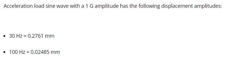
      2.       You applied a 2.5 mm Nodal Displacement, but you didn’t mention the start and end frequencies for the analysis. This is important because it directly affects the acceleration applied to that node. A displacement describes the motion of the node. The acceleration of that node has a frequency squared term.

      Consider a SDOF oscillator with a base excitation frequency of 10 Hz. For the base to have a displacement of about 2.5 mm, the base acceleration is 0.1 G.

      But at an excitation frequency of 100 Hz, the base must have an acceleration of 100 G to maintain a 2.5 mm displacement.  Can the vibration source really generate those accelerations?

      Now consider the alternative, using an applied force instead of a displacement. In the example above, at an excitation frequency of 10 Hz, the force causes a displacement of 2.5 mm and an acceleration of 0.1 G. But now at 100 Hz, the force is constant, so the displacement must go down to 0.0025 mm and the acceleration remains at 0.1 G.

       3.       I don’t know what a longitudinal loss factor is. Constant Structural Damping Coefficient is divided by the excitation frequency and multiplied by the Stiffness Matrix to form the Damping Matrix.  Damping Ratio is not used in Full Harmonic Analysis. Damping Ratio is used in MSUP Harmonic Analysis. This is because these to analyses use different governing equations. In Full Harmonic, you can select values of the Rayleigh Damping coefficients of Alpha and Beta, also called the Mass and Stiffness Coefficients, and use an equation to compute the equivalent Damping Ratio.

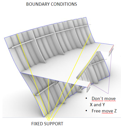
      4.       Fixed BC add a lot of stiffness to the model and are to be avoided. Remote Displacements, Behavior = Deformable allows a collection of edges to be constrained, in the average, without adding stiffness.  Use one on each major cutting plane.

      5.       If you do MSUP Harmonic Response, then the BC come from the Modal analysis.  If you do Full Harmonic Response, then you must add the BC yourself.

      6.       What is the source of vibration? How is it specified or measured?  Over what frequency range is it measured?

    • Geovanna Quinde
      Subscriber

      Hello Peter, Can you help me with this please?

      I want to apply a base excitation displacement that represents the engine vibration in a machinery room. The engine power is 3070 HP at 1050 rpm, and the analysis will be done in this range of frecuencies: 14 - 34 Hz. 

      I saw this reply, do you have any source that establishes what is the amplitude of base displacement adequate for a frecuency? 

      /forum/forums/reply/109903/


    • peteroznewman
      Subscriber

      Hello Geovanna,

      This website has a good explanation of the equations for simple harmonic motion.

      If you start with a specification on the acceleration amplitude of 1G = 9810 mm/s^2, use the third set of equations that has the constant C for the amplitude.

      In the example above, f = 30 Hz so w = 2*Pi*30 = 188.5 radians/sec.

      The displacement amplitude is C/w^2 = 9810/188^2 = 0.276 mm.

      In the description of your project, you mention the HP of the engine, and the RPM, but that doesn't help to define either an acceleration or a displacement base vibration amplitude that engine creates. The best way to know the base vibration amplitude that engine creates is to fasten an accelerometer to the base and record the vibration using a data acquisition system. I have experience with that instrumentation if you would like to discuss it further.

Viewing 5 reply threads
  • The topic ‘How to apply a vibration displacement only in a section of a structure?’ is closed to new replies.