-
-
August 31, 2020 at 7:06 am
Rameez_ul_Haq
SubscriberCan anyone kindly guide me on to know what is the default solver element type for joints other than fixed, such as revolute or translational? How can I change the solver element type of the revolute joint so that the two joined surfaces (reference and mobile) behave the same way as revolute joint but there is no transfer of forces and moment between them? How can make use of the constraint equations using remote points for this action?nSIDE QUESTION: I just want to ensure that does the location of remote point change during the analysis according to the scoped surface, when it moves or deforms?n -
August 31, 2020 at 11:47 pm
peteroznewman
SubscriberYour questions do not make sense. Please reply with a complete description of what you want to simulate, and we can discuss options for how to do that. Start with the full physical reality of the situation: the geometry, loads, supports, frictional contact, and we can discuss how to idealize it. Maybe no joints or remote points are needed.nn -
September 1, 2020 at 1:35 pm
Rameez_ul_Haq
SubscriberPlease observe the figures below.nAll of the joints are fixed. First and last joint has a solver element type of Contact/Direct. From my understanding, this solver element type doesn't trasnfer any force/moment between the reference and mobile faces, although the motion between them is still fixed joint. How can I achieve this (i.e. non-transfer of force and moment) when I am modelling a fixed joint using remote points and constraint equations?nPlus, I cannot see any solver element type option in a revolute joint. I was wondering why is that? How can I achieve the non-trasnfer of forces and moments between the reference and mobile faces, and the same time making the joint as revolute? How can I do this using remote points and constraint equations?n
-
September 1, 2020 at 5:26 pm
Rameez_ul_Haq
SubscriberSIDE QUESTIONS: 1) I just want to ensure that does the location of remote point change during the analysis according to the scoped surface, when it moves or deforms?n2) As we know that the joint co-ordinate system's orientation translates/rotates when the scoped faces change their location in space during analysis. Are the joint reaction forces given according to the orientation of the co-ordinate system before the analysis or after the analysis?n -
September 1, 2020 at 9:08 pm
peteroznewman
SubscriberThank you for a specific example. If you delete the mesh, and save the project, you can do a File, Archive and create a .wbpz file. Put that in a .zip file and you can attach that to your reply with the paperclip icon as long as the file size is < 50 MB. That will let me look at the model results in detail. Make sure to say what version of ANSYS you are using.nWhat was the Behavior of the Remote Force of 7500 N? Was it Rigid or Deformable? That is a critical question. What does the part that interfaces to those six holes look like? If it is a large thick solid body of equal or higher modulus, and fasteners clamp those holes onto a solid flange, then a Rigid is a reasonable approximation.nThe four Fixed Joints are there to represent a fastener that would clamp the two plates together, is that correct?nSIDE QUESTION 1. The location of the remote point changes as the face it is scoped to deforms.nSIDE QUESTION 2. If the Joint Coordinate System rotates during the solution, Probing the Joint Forces will be to the current orientation of the Joint Csys. It is good to build small models that answer these kinds of questionsn -
September 2, 2020 at 7:20 am
Rameez_ul_Haq
SubscriberHello sir. I am not allowed to post the ANSYS file here. If I was, I would be glad to do so.nThe remote force is applied to the six holes in a deformable fashion. But I checked by changing the behavior of the remote force and the fixed joint reaction forces on each of the four holes does change, although still not sure how is it being done behind the closed doors of ANSYS solvernI have changed the behavior of the fixed joints from deformable to beam to rigid, as well as changing the remote force behavior from deformable to rigid, but still the Contact/Direct solver element type gives me zero joint reaction force at those joint where it is chosen. And I actually want zero reaction joint forces in the fixed joints where I allocated its solver element type as Contact/Direct instead of Joint Element.nNow my question is, as I have also mentioned in my past comment, how can I do this using the remote points and constraint equations?nHow can I do this in revolute joint? And how can I model a revolute joint using remote points and constraint equations which gives me zero joint reaction forces, so that no transfer of force and moment occurs between the scoped faces.n -
September 2, 2020 at 9:08 am
Rameez_ul_Haq
SubscriberSIDE QUESTION 1: If the remote point will change its location then it means that the remote force attached to that remote point will also rotate/translate according to the change in location of remote point, during the analysis right? because we know this that the force doesn't change its location or orientation during the analysis unless it is applied as a pressure on the scoped surface n -
September 2, 2020 at 10:38 pm
peteroznewman
Subscriber
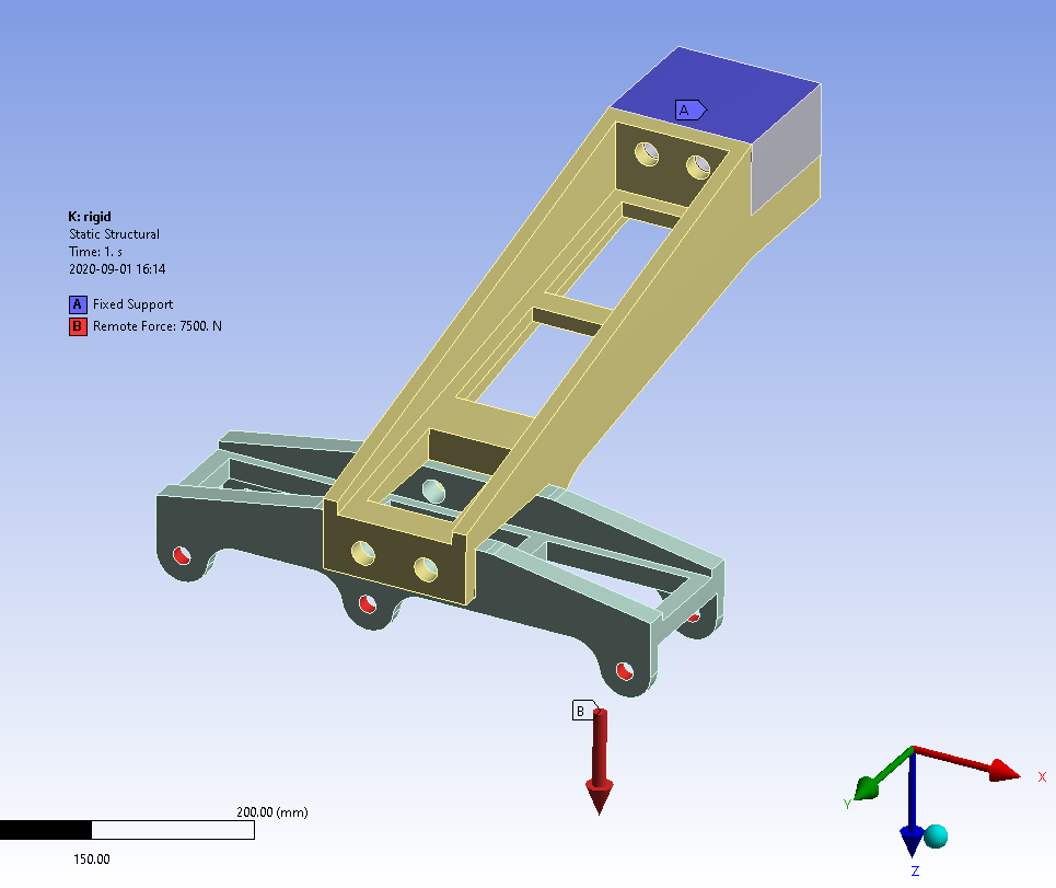
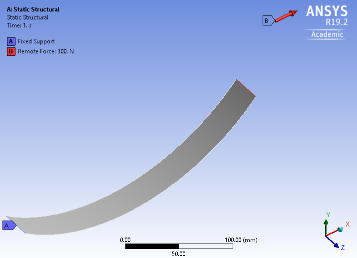
A joint that transmits no forces in any direction and no torque about any axis is not a joint. The definition of a joint is a connection. No force and no torque is no connection.nIn your other post, I see you are using ANSYS 19.2, is that correct? I have that version on this laptop, but it is the academic version so I can only solve small models.nSIDE QUESTION 1nI made a small simple model to show you a remote point that moves during the solution. The force is applied at a rigid remote point scoped to the end of the curved beam.n
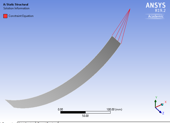
nYou can see the CE elements that connect it to the end if you click on the Solution Information folder then on the Graphics tab.n
nDue to large deformation effects, the Remote Point moved with the end of the cantilever, but the force did not rotate as the tip deflected, the force stayed aligned with the X axis because it is not a follower force, though that is possible if that is what you want.n
n
-
September 3, 2020 at 5:48 am
Rameez_ul_Haq
SubscriberThank you sir for your explanation. nCan you kindly define the meaning of Contact/Direct and Joint Element, and difference between these two?n -
December 14, 2020 at 12:01 pm
Rameez_ul_Haq
SubscriberArray, so the force direction keeps on applying the load to the remote point in the same direction which it was assigned initially, even though the remote point is moving/rotating in a very different direction during the analysis; am I correct sir?nInstead, if I want to make a follower force in ANSYS, how do I do it?nYou mentioned this in one of your comments here, SIDE QUESTION 2. If the Joint Coordinate System rotates during the solution, Probing the Joint Forces will be to the current orientation of the Joint Csys. So by current, you mean after the solution is finished, or before the start of solution i.e. the time we are creating a joint connection? The joint co-ordinate system that we will see after the solution has finished, under the joint probe, will be the translated/rotated co-ordinate system after the solution or its orientation would be the same as before the analysis at the time of making the joint?nWhat to do if the joint probe gives the forces under the rotated/translated co-ordinate system? Is there a way to know the rotation that has happened between the oreintation of the joint co-ordinate system before and after the analysis? How can I get the joint forces under the global co-ordinate system?nAnd also, can you kindly define the meaning of Contact/Direct and Joint Element, and difference between these two?nThanks alot Sir. -
December 14, 2020 at 8:48 pm
peteroznewman
SubscriberThe force direction keeps on applying the load to the remote point in the same direction which it was assigned initially is correct.nLink to answer Follower Force question: /forum/discussion/20522/how-to-setup-a-follower-force-for-a-cantilever-beamnI will try to come back and answer the other questions on another reply. -
December 15, 2020 at 3:15 am
peteroznewman
SubscribernFollowing up on the previous post, has provided the answer to your other question in the link below:n/forum/discussion/22859/express-the-loads-in-the-global-coordinate-system#latestnAs to your last question, Joints are Joints. I don't know what you mean by Contact/Direct.n -
December 15, 2020 at 7:10 am
Rameez_ul_Haq
Subscriber,I mean the solver Element type option within a fixed joint has two options, first is joint element and the second is contact/direct. I want to understand the difference between these two please?nI have read this link, but still it was somewhat helpful. I have already commented there to get things clarified a little more. n/forum/discussion/22859/express-the-loads-in-the-global-coordinate-system#latestnn -
December 15, 2020 at 10:49 pm
peteroznewman
SubscribernI looked in the ANSYS Help for a Fixed Joint and it was not very helpful, maybe you looked there and were unsatisfied also.nThe effect of a Fixed Joint can be realized in two ways.n1) Create MPC184 element and constrain all DOFn2) Create Contact and Target elements as if you had defined Bonded Contact.nThis is analogous to when you use Bonded Contact in Mechanical, there are 5 formulations, and one of them is MPC while three create Contact and Target elements.nYou can confirm this by defining two Fixed Joints in two different ways, then instead of doing a Solve, write out the ANSYS input data file and look at the APDL code.n
-
Viewing 13 reply threads
- The topic ‘How to add solver type as Contact/Direct to revolute joint?’ is closed to new replies.
Ansys Innovation Space
Trending discussions
Top Contributors
-
3572
-
1188
-
1076
-
1063
-
952
Top Rated Tags
© 2025 Copyright ANSYS, Inc. All rights reserved.
Ansys does not support the usage of unauthorized Ansys software. Please visit www.ansys.com to obtain an official distribution.