TAGGED: 1d-beam, beam, beam-analysis, beam-element, beam-elements, beam-tool
-
-
May 20, 2023 at 7:51 pm
KulTigin00
SubscriberHello Everyone,
I have a little question for you.
I modeled the system you see in the images using 1-D beam elements and using 2-D elements with the same boundary conditions.
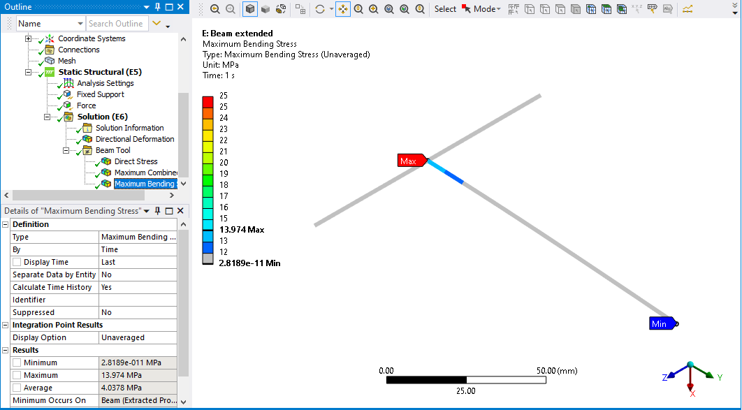
This is the Maximum Bending Stress - Maximum Combined Stress result of my 1-D model.
This is the Equivalent Stress result of my 2-D model.
As you can see, there is about a two times difference between them. This situation does not change no matter what the problem is. In other words, when I try different systems with different boundary conditions, I see a two times difference between them.
What is the theoretical explanation for this? What material property should I compare when interpreting my 1-D FEA results?
In my opinion, my result should not change whether I model this system in 1-D, 2-D or 3-D.
Thanks,
KulTigin
-
May 21, 2023 at 7:33 pm
peteroznewman
SubscriberHello KulTigin,
Beam models are the highest level of abstraction and have the most simplifying assumptions. For example, the uniform cross-section cannot change due to deformation. Shell models are a middle level of abstraction and have fewer simplifying assumptions but have limitations, such as they are only appropriate for thin-walled structures. Solid models have the lowest level of abstraction and the fewest simplifying assumptions and limitations. Each type of model is useful for different purposes. For example a beam model may be easier to parameterize for design optimization than the shell or solid model.
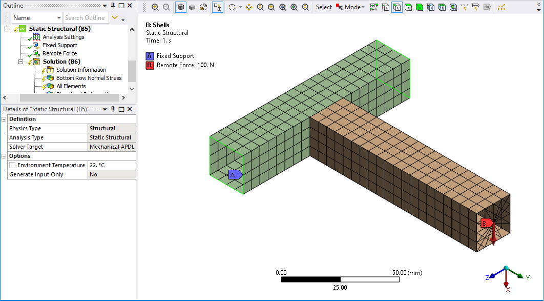
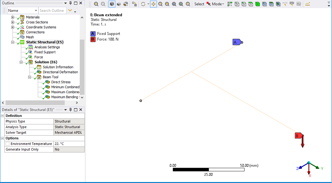
Your geometry has one beam connecting at a right angle to the center of another beam in what is called a Tee-intersection. In your beam model, the vertical beam was extended to reach down to the neutral axis of the horizontal beam. In the shell model, the vertical beam ends on the top of the horizontal beam. I made a similar Tee-intersection model and meshed it with shells and beams to illustrate my results.
The beam model is most honestly represented as a stick model.
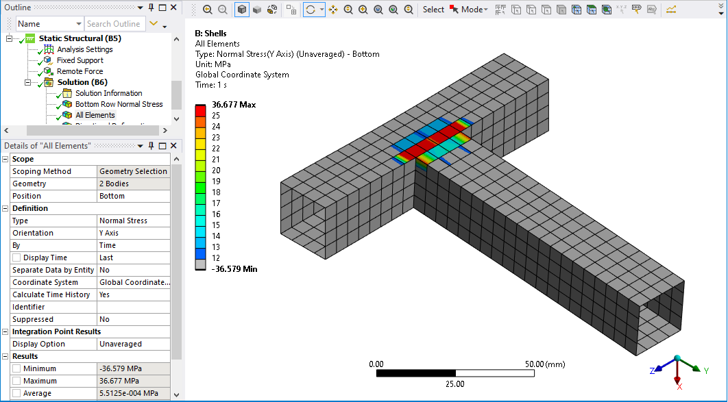
When comparing stress results you must compare similar stress quantities. The Beam Bending Stress is along the length of the beam at the extreme fiber. That direction of stress is the Normal Stress in the Y direction in my shell model.
The shell element Normal Stress in the Y direction for my model is shown below. Notice that the highest stress in the shell model is in the row of elements in the left tube, while the right tube has lower values of stress. The beam model can’t grab elements on the side of the left tube like it can in the shell model because the tube has been idealized to a beam element, so the highest stress in the shell model is not relevant to compare with the beam model.
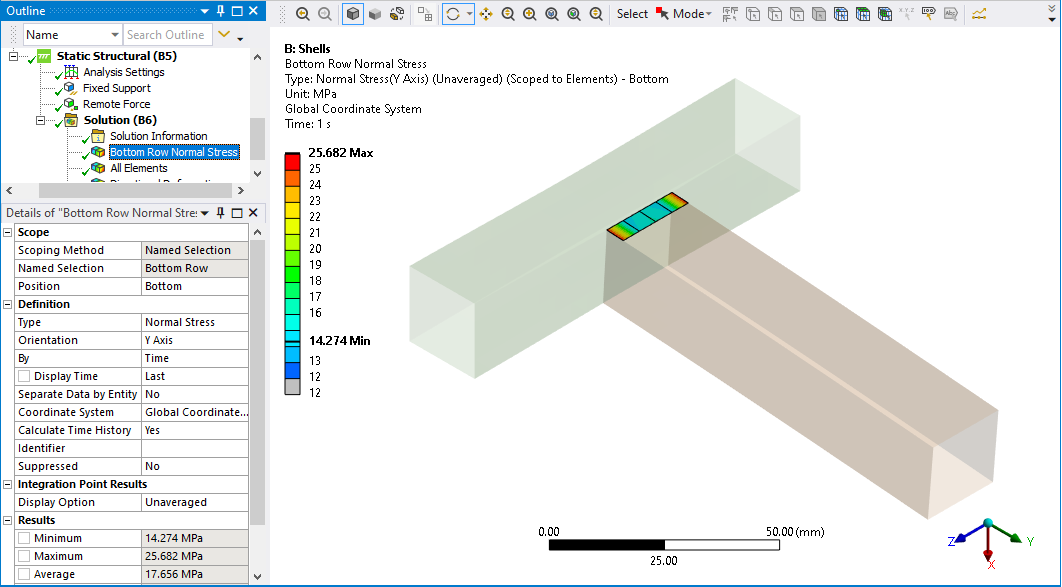
Look at the stress in just the 4 elements at the bottom of the right beam.
In the shell model, the minimum stress value of these four elements is 14.3 MPa and the average is 17.6 MPa. The beam model stress results below show the maximum value is 14.0 MPa which is at the center of the left tube, but the shell model doesn’t connect there, it connects at the surface of the tube. The beam element at a similar location to the shell model has a stress between 12 and 13 MPa. Note also that the beam element has a single stress value over the cross-section, while the shell model shows variation from the edges of the section to the center of the section, which the beam model can’t do.
I hope this helps to explain that the difference between the stress of the beam and shell models is in the range of 20%, not 100%, and that because of the different assumptions and modeling idealizations, you should not expect to get the same results from a shell and a beam model for this geometry.
Regards,
Peter
-
May 22, 2023 at 4:59 am
KulTigin00
SubscriberHello Peter,
Thank you for your detailed answer. There could be no better answer to my question than this. It's amazing to be able to get support from you.
I have one more small question. You know, after an FEA simulation is done, the stress values are compared to material properties. For example, we compare the equivalent stress results with yield stress in static analyses and fatigue strength in vibration analyses. When beam modeling is performed in vibration analyses, we obtain normal stress and shear stress values.
Which stress values should I compare with the fatigue strength of the material in vibration analyses? I would like to ask the same question for static analyses.
Regards,
KulTigin
-
May 22, 2023 at 2:03 pm
peteroznewman
SubscriberHello KulTigin,
It is a pleasure to reply to someone who asks clear questions and provides sufficient detail in the post including geometry images.
Evaluation of the stress in a structure to determine a Safety Factor on Yield or Fatigue is rarely done on a beam model because the idealization of the geometry hides the true peak stress. Even a shell model can have an inaccurate peak stress. Take your example of the Tee-intersection. The vertical part would be welded to the horizontal part. A full penetration weld can bond the full wall thickness and provide a weld bead on the outside edge that is not in the shell model. In that case, a solid model can include the material added by the weld bead which may be further shaped by grinding.
If you need to calculate the Equivalent Stress in a Beam model, you must do some hand calculations using beam equations to get the six components of stress at a point of interest. The beam tool will only give you axial stress and bending stress, which add together in the Combined Stress output, and that gives you one component of normal stress along the beam. You can request Beam Results and get one component of the shear stress.
Look at the horizontal beam in your beam model. That has a significant torsion load that creates a significant shear stress, but the shear stress from Beam Results does not capture this shear stress because it is on a different plane. You have to obtain the Reaction Moment on the Fixed Support, and use that along with the equation for shear stress in a beam under torsion to hand calculate that shear stress component.
Once you have all six components of stress (3 normal and 3 shear) use the Von Mises equation to get Equivalent Stress.
You can see why the initial evaluation of yield and fatigue safety factors would be done in a shell model which can calculate the Equivalent Stress and Safety Factor for you with no hand calculation. Depending on the location of the peak stress, a detailed solid model may be required.
Regards,
Peter
-
- The topic ‘How should 1-D FEA analysis be evaluated?’ is closed to new replies.


-
5159
-
1836
-
1387
-
1249
-
1021

© 2026 Copyright ANSYS, Inc. All rights reserved.

