-
-
March 22, 2020 at 9:37 pm
DianaLeandro
SubscriberI’m performing a structural simulation, where forces are applied to a musical instrument of strings, made of wood and subsequently see the deformation of it, but I want to know if the total deformation presented in the results is a maximum point (not ideal) before material rupture, or if it is the maximum (real) deformation point that reaches the material.
-
March 22, 2020 at 9:58 pm
peteroznewman
SubscriberPlease use the Insert Image button and reply with an image of the model and the Total Deformation result. You have to create a file of a screen snapshot that you can save using the Snipping Tool.
-
March 23, 2020 at 5:25 pm
-
March 23, 2020 at 9:05 pm
peteroznewman
Subscriber
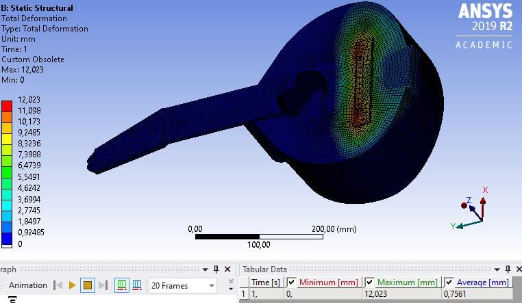
Most of the instrument has deformed very little, so the average deformation is small. You might as well ignore that value.
The maximum deformation is of interest. Under Analysis Setting, did you turn on Large Deflection? If not, turn that On and Solve. Compare what the maximum deformation is after that solves. It may be less.
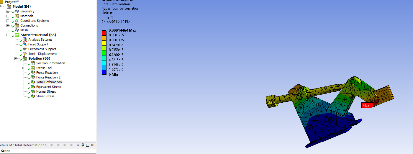
Maximum deformation is not helpful to predict material failure. Maximum stress is what to look at to predict material failure. Material is tested in a tensile testing machine that records the force and displacement of the sample, then those are converted to Stress and Strain. When the material fails, there is a maximum value of stress that is called the Ultimate Tensile Strength (UTS).Â
Plot the Maximum Principal Stress and compare that maximum value with the UTS to decide if failure has occurred. You don't see the failure in the plot, you decide if it would have failed or not.
In the reference above, they use Modulus of Rupture, which is like UTS. If your Maximum Principal Stress is greater than Modulus of Rupture, then the wood has failed if it is less, then the wood can carry that load.
Â
-
March 24, 2020 at 3:44 am
DianaLeandro
SubscriberI've already modified the parameter you told me and if the maximum deformation was reduced.Â
Â
 As for the mechanical properties of the wood already implemented previously, but the deformation is still very high, the maximum deformation of about 5 mm is expected.Â
Â
Would you know that another aspect can be modified to reduce deformation
Â
How can I plot UTS results?
-
March 24, 2020 at 3:54 am
-
March 24, 2020 at 12:34 pm
peteroznewman
SubscriberGood to see you have an orthotropic material defined.
I see the high stiffness direction of this material is along the X direction, which for wood is parallel to the grain.
What direction does the grain of the wood run on the surface that is deforming excessively? I expect it is the Global Y axis?
Please plot the Element Triads and show that the element coordinate system X axis is aligned with the grain direction of the wood on that surface.
-
March 25, 2020 at 5:39 pm
DianaLeandro
SubscriberThe major deformation is presented on the z-axisÂ
The Elements traids:
Peter, do you know how to fix this error?
"At least one body has been found to have only 1 element in at least 2 directions along with reduced integration. This situation can lead to invalid results or solver pivot errors. Consider changing to full integration element control or meshing with more elements."
Â
-
March 25, 2020 at 6:09 pm
peteroznewman
SubscriberThe best way to fix this error is to replace all the thin-walled solids with midsurface geometry and mesh with shell elements instead of solid elements. When you do that, the shell element local coordinate system will no longer line up with the global axis as it does for the solid elements.
Another way to fix this error is to slice all the thin-walled solids up so that you can sweep elements through the thickness.
You didn't answer my question:Â What direction does the grain of the wood run on the surface that is deforming excessively?
-
March 25, 2020 at 9:19 pm
DianaLeandro
SubscriberThe direction of the grain of the way is in y-axis, because when cutting the piece of wood, they do it radially, so that the force is generated perpendicular to the fiber.Â
Â
 With regard to that I wanted to ask you one thing, how the direction of the wood is on the shaft and, it is expected that this is the one that handles the Young module with the most value, I wanted to change those parameters by reversing the values in the properties of the materials, but it does not seem to be allowed to use a value on the y-axis (of the Young module) greater than the x-axis. Do you know how if there is any way to solve that?
-
March 26, 2020 at 12:50 am
peteroznewman
SubscriberDo what was done in this example to align the original material you defined at first so that the material X axis is aligned with the global Y axis.
-
March 26, 2020 at 8:50 pm
-
March 26, 2020 at 9:00 pm
peteroznewman
SubscriberHi Diana, Good to hear. You can mark this Discussion as Solved by clicking on the Is Solution link (while you are logged in) below the post that best answered your question.
-
February 14, 2021 at 9:51 pm
eaoloo
SubscriberThis is a stress analysis on a clamp down made of stainless steel. The material has a safety factor of 1.51 and the max force reactions is 300lbf. The joint displacement value is 1.9094e-4.nDiscuss the resultn1. Is the total deformation distribution patterns as expected?n2. Is the region with the max total deformation as expected? If not why?nn
-
February 14, 2021 at 11:59 pm
peteroznewman
SubscribernYesnYesn
-
- The topic ‘How is total deformation and average deformation interpreted?’ is closed to new replies.
-
5074
-
1797
-
1387
-
1248
-
1021
© 2026 Copyright ANSYS, Inc. All rights reserved.


