

TAGGED: designmodeler, geometry, velocity-inlet
-
-
July 8, 2021 at 7:48 am
Mecha
SubscriberJuly 8, 2021 at 8:17 amAmine Ben Hadj Ali
Ansys EmployeeIf you will consider the inner part of the annulus you will have at least two fluid domains. Just create reasonable naming for the boundaries to seamlessly identify them in the setup afterwards.
July 8, 2021 at 8:17 amaitor.amatriain
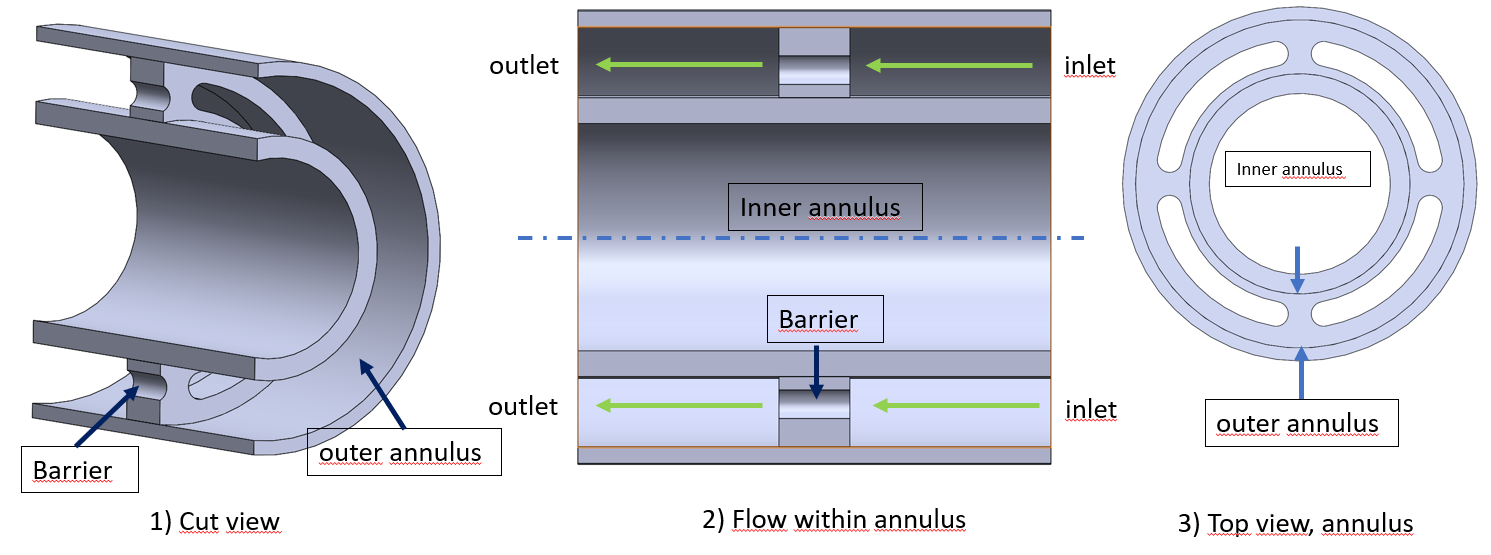
SubscriberIn order to simulate the flow in the outer annulus, you need the geometry of the fluid part, while you have the one of the solid part.
Once you have the geometry of the fluid part, in ANSYS Meshing you can set the names of the boundaries by creating Named Selections. If you decide to use Fluent Meshing, then you can do the same by creating Groups in SpaceClaim.
July 9, 2021 at 11:30 amSubscriberThank you for your help Possible Setup Conflict?
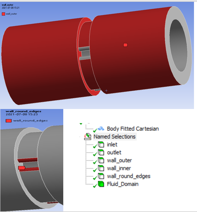
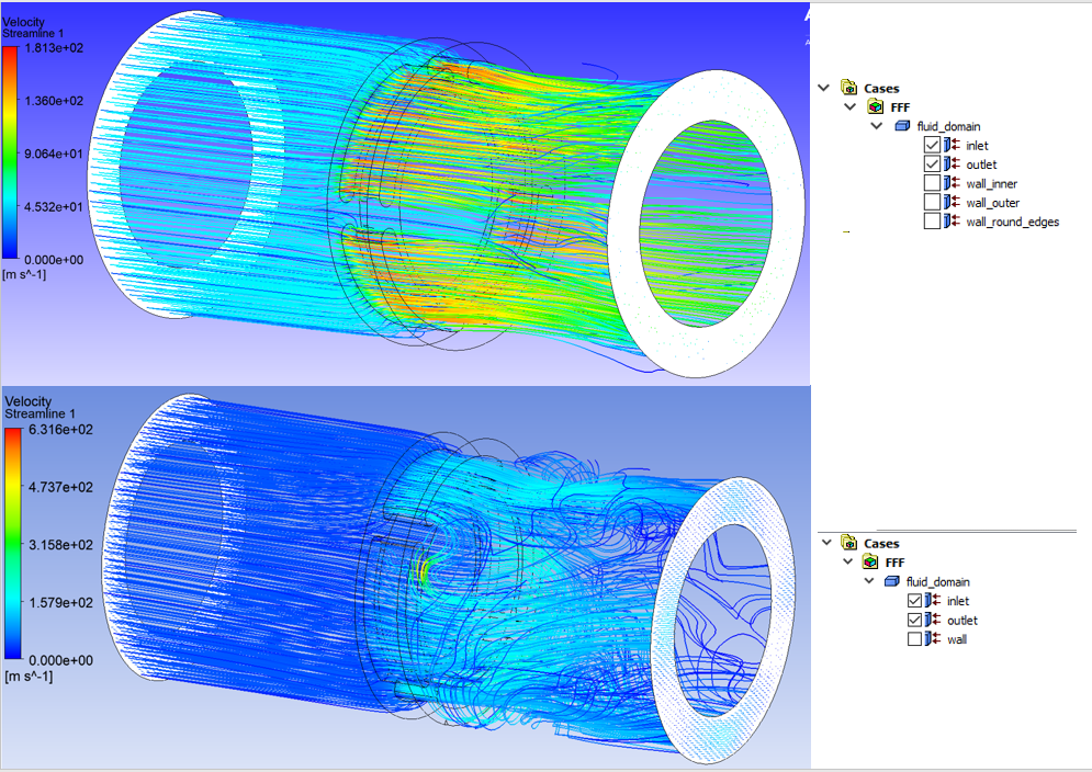
I have successfully obtained some test result(s), however, I am a bit confused. Figure_1 display how I set up the names for inlet/outlet and walls for one case, (I hope its explanatory enough). In Figure_2, I have compared the same solver setup with another name setup, (inlet/oulet and wall only).
Question:
Should the selection of how I apply my names to my boundary conditions affect the results and what can be the reason for the different results?
My opinion is that the the last picture of Figure_2 is the most realistic one due to the turbulence that would be caused after exiting the "barrier". In a generic view, which of them seem most reasonable?
Viewing 3 reply threads- The topic ‘How do i obtain the proper design for a multi-inlet/outlet flow?’ is closed to new replies.
Innovation Space Trending discussions
- air flow in and out of computer case
- Varying Bond model parameters to mimic soil particle cohesion/stiction
- Eroded Mass due to Erosion of Soil Particles by Fluids
- I am doing a corona simulation. But particles are not spreading.
- Centrifugal Fan Analysis for Determination of Characteristic Curve
- Guidance needed for Conjugate Heat Transfer Analysis for a 3s3p Li-ion Battery
- Issue to compile a UDF in ANSYS Fluent
- JACOBI Convergence Issue in ANSYS AQWA
- affinity not set
- Resuming SAG Mill Simulation with New Particle Batch in Rocky
Top Contributors
-
peteroznewman
 4062
4062 -
scabo
 1487
1487 -
Dennis Chen
 1308
1308 -
javat33489
 1156
1156 -
Shyam Prasad V Atri
1021
Top Rated Tags
© 2025 Copyright ANSYS, Inc. All rights reserved.
Ansys does not support the usage of unauthorized Ansys software. Please visit www.ansys.com to obtain an official distribution.
-


The Ansys Learning Forum is a public forum. You are prohibited from providing (i) information that is confidential to You, your employer, or any third party, (ii) Personal Data or individually identifiable health information, (iii) any information that is U.S. Government Classified, Controlled Unclassified Information, International Traffic in Arms Regulators (ITAR) or Export Administration Regulators (EAR) controlled or otherwise have been determined by the United States Government or by a foreign government to require protection against unauthorized disclosure for reasons of national security, or (iv) topics or information restricted by the People's Republic of China data protection and privacy laws.


