Electronics

Electronics

Topics related to HFSS, Maxwell, SIwave, Icepak, Electronics Enterprise and more.

How do i find out resistance of coil in ansys maxwell transient 3d solver?

    • s3740222
      Subscriber
      How do I find out internal resistance of coil in Ansys Mxwell transient 3d solver? I designed a generator and in excitation I added coil and external circuit . I want to know the inductance and resistance of coil. So that i can add same value of resistance as load resistance to get maximum power output based on Maximum power transfer theorem.nAlso, in Motion setup when i give sinusoidal input velocity as 2*sin(2*pi*time) then output should be sinusoidal voltage and current. But I am not getting sinusoidal. Please help.n
    • s3740222
      Subscriber
      .

      When i give velocity as 2*sin(2*pi*time) I get this output. Why not sinusoidal ?

      .
    • icellb1
      Ansys Employee
      Hi, Array ,
      If you are just interested in resistance and inductance of your coils, you can run a simulation with eddy current solver with a simple internal excitation you defined. Make sure to assign parameter-->matrix before analyzing. In result-->solution data you can view R and L values under matrix tab.
      The resistance and inductance added in external circuits are extra R and L you added besides the internal R and L of the coil, for example, end connection R. These are the ones that cannot be identified by the solver with the geometry and material properties you input in the Maxwell model window.
    • Navya Chode
      Forum Moderator
      Hi Pooja,
      Shape of output voltage is dependent on rotor construction, placement of magnets and on the winding distribution. If you have a proper 3 phase distributed winding and magnet arrangement (in case of PM generator) or proper pole shape (in case of wound field generator) then you can get a sinusoidal voltage.
      You should run the generator at certain constant speed to really check if your output voltage is sinusoidal in stable condition.
      By defining a sin function as speed you are actually introducing fluctuation in speed at different time intervals and it will impact the magnitude of your output voltage and this may eventually look like non uniform shape but will not give an idea of how your generated emf looks like.

      Regards,
      Navya

    • s3740222
      Subscriber
      Thanks icellb1 and Navya !!
      Navya i am making linear generator to work in ocean thats why i am trying to give sinusoidal input velocity to the translator.
      Also, Can you please tell me is there any block of adding Sinudoial input in the external circuit so that i will get sinusoidal output. Like In MATLAB we have one sinusoidal input box which we can define and the values will come out as sinusoidal only. Is there any such way in ANSYS ?
      Thanks again Navya. You have always been so kind in replying.
    • s3740222
      Subscriber
      Hi Navya.
      Can you please also tell how to define proper winding in ansys maxwell transient. The way I do Right now is, I define a section in coil and assign coil terminal to it. After assigning coil terminal I add winding and add this terminal to winding. Then I assign excitation as External and add external circuit. How would i know that the winding is done properly ,I mean whether its Distributed or not.
      Thanks heaps. You are solving my problems.
    • Navya Chode
      Forum Moderator
      .

      @pooja,

      I am assuming you have permanent magnets on your slider.

      External circuit you are defining is on the armature with winding. So, I don't think you should add anything to this external circuit to get the sinusoidal induced voltage(output) as it may not reflect the practical case.

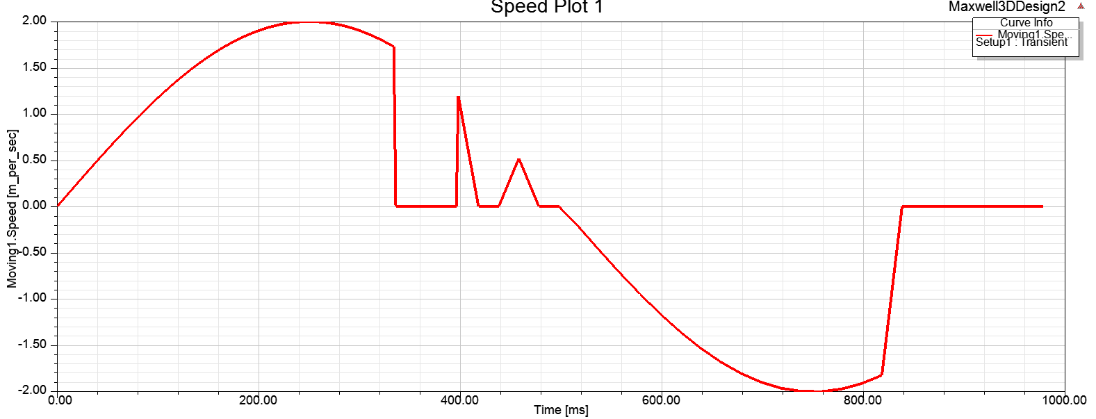
      As, a first check, can you assign a constant velocity to your slider and check if you are getting a constant and linear output voltage ?. Depending on this result you will understand how your slider moment is translating in to output voltage and whether it will really follow the velocity function. The reason I am asking you to do this is, as you know a linear generator is just a unrolled rotary generator and similar to rotary generator it should generate similar output voltage waveform depending on the construction.

      I don't have any details on how your model is and as an Ansys employee I cannot involve in your project work or home work or design directly except for tool support. I can suggest you the following.

      1. Do the above check with constant velocity.
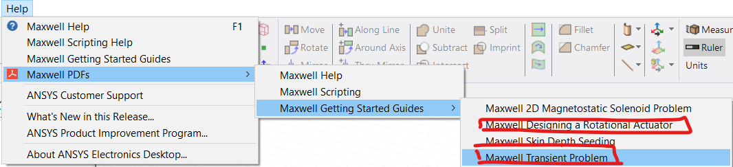
      2. The way you are assigning the winding and excitation seems to be correct. You can also refer to the below Maxwell help documents for more information on setting up a transient simulation or defining winding.

      .
    • s3740222
      Subscriber
      Thanks Again for your quick response.
      I tried running with constant speed and I am getting sinusoidal output but I need to get sinusoidal output with sinusoidal velocity based on my project requirement.
      I can understand that you cannot help me beyond certain point but this is related to ANSYS only. I think there is some problem with the software as when you give sinusoidal velocity the output should come out as sinusoidal according to the literature. But in Ansys this is not happening. I am getting triangular shaped output. In my case the magnets and coil both are on the moving part.
      Also, regarding finding out the R and L of the winding coil in transient solution, I can use eddy current solver specifically to find out the R and L value and I can use the calculated values from eddy current solver into Transient Solver.
      Please clear my doubt regarding Ansys.
      Hopefully, i will find out the answers to my questions.
      Thanks Navya. You really helping me alot.
    • Navya Chode
      Forum Moderator
      Hi Pooja,
      The statement you are saying " you give sinusoidal velocity the output should come out as sinusoidal" is not correct. Your design/generator might not be same as the literature you are referring. Please cross check with the reference design.
      This is because, as you saw, you are getting a sinusoidal output from constant velocity. What do you infer from this?
      This is happening because you have a spatially distributed winding and a constant magnetic flux is cutting the conductors.
      This shows that tool is working correctly and there is nothing wrong with the output you are getting.
      It will be inappropriate for me to comment why you are expecting a sinusoidal velocity function to generate a sinusoidal output with out knowing about your design.
      I didn't understand your statement "In my case the magnets and coil both are on the moving part"
      If possible upload some screen shots of your model with some annotations on it for me to understand your model and setup. With out which, at this stage, there is high chance that I will be making wrong assumptions about your design.
      Also where are you using this L & R in transient simulation? Provide screen shots for everything from now on to avoid misinterpretation.

      Regards
      Navya
    • s3740222
      Subscriber
      Thanks Navya for your response.
      I sorted this out.
      Thanks again.
    • Vanna855
      Subscriber
      .

      Dear sir,

      I am working on a generator and I don't know how to get Eddy current loss. could you please tell me how to find it??

      .
Viewing 10 reply threads
  • The topic ‘How do i find out resistance of coil in ansys maxwell transient 3d solver?’ is closed to new replies.