Fluids

Fluids

Topics related to Fluent, CFX, Turbogrid and more.

How create and use Profile txt file as a boundary condition in FLUENT?

    • José Mantovani
      Subscriber

      Hello guys!


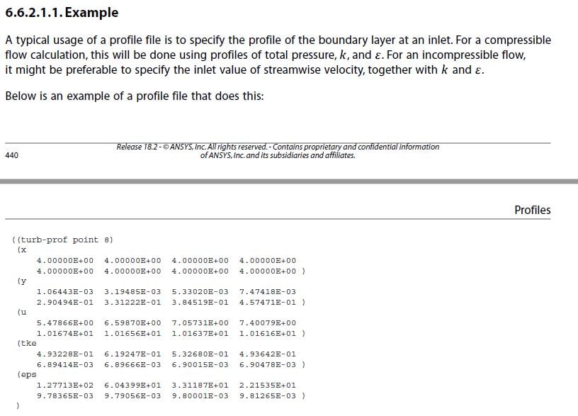
      I need to create a txt file (velocity profile) to use as boundary condition in 2D simulation using FLUENT. Look, this is not a UDF, this is a txt file... Someone can help me? With some file model or video tutorial? I need know how to create ths file with velocity profile and turbulence information. 


      The archieve: 


      Re_delta* = 1000, Re_theta = 670, Re_delta+ = 325.


      Mean and mean-square fluctuations:


        J    y/delta      y+           U+         uu+          vv+         ww+        uv+


        1  7.9361E-04  2.5864E-01  2.5869E-01  1.0687E-02  7.7580E-07  4.8148E-03 -2.0170E-05


        2  1.9512E-03  6.3591E-01  6.3602E-01  6.4130E-02  2.4659E-05  2.6552E-02 -3.0967E-04


        3  3.6251E-03  1.1814E+00  1.1811E+00  2.1866E-01  2.4991E-04  8.0063E-02 -2.0531E-03


        4  5.8172E-03  1.8958E+00  1.8922E+00  5.5397E-01  1.3473E-03  1.7426E-01 -8.6438E-03


        5  8.5301E-03  2.7800E+00  2.7618E+00  1.1537E+00  4.8586E-03  3.0742E-01 -2.6780E-02


        6  1.1767E-02  3.8349E+00  3.7697E+00  2.0565E+00  1.3253E-02  4.6777E-01 -6.5352E-02


        7  1.5532E-02  5.0619E+00  4.8781E+00  3.1983E+00  2.9468E-02  6.4116E-01 -1.3083E-01


        8  1.9829E-02  6.4624E+00  6.0319E+00  4.4055E+00  5.6196E-02  8.1625E-01 -2.2210E-01


        9  2.4664E-02  8.0381E+00  7.1703E+00  5.4726E+00  9.5323E-02  9.8598E-01 -3.2983E-01


       10  3.0043E-02  9.7910E+00  8.2412E+00  6.2592E+00  1.4761E-01  1.1473E+00 -4.4081E-01


       11  3.5972E-02  1.1723E+01  9.2108E+00  6.7224E+00  2.1258E-01  1.2962E+00 -5.4343E-01


       12  4.2459E-02  1.3837E+01  1.0065E+01  6.8949E+00  2.8851E-01  1.4285E+00 -6.3084E-01


       13  4.9512E-02  1.6136E+01  1.0806E+01  6.8461E+00  3.7247E-01  1.5420E+00 -7.0102E-01


       14  5.7140E-02  1.8622E+01  1.1444E+01  6.6460E+00  4.6087E-01  1.6344E+00 -7.5503E-01


       15  6.5353E-02  2.1299E+01  1.1993E+01  6.3545E+00  5.4993E-01  1.7056E+00 -7.9554E-01


       16  7.4163E-02  2.4170E+01  1.2468E+01  6.0193E+00  6.3615E-01  1.7579E+00 -8.2536E-01


       17  8.3581E-02  2.7239E+01  1.2881E+01  5.6693E+00  7.1679E-01  1.7923E+00 -8.4677E-01


       18  9.3621E-02  3.0511E+01  1.3244E+01  5.3236E+00  7.8985E-01  1.8123E+00 -8.6175E-01


       19  1.0430E-01  3.3990E+01  1.3568E+01  4.9960E+00  8.5407E-01  1.8233E+00 -8.7156E-01


       20  1.1562E-01  3.7682E+01  1.3860E+01  4.6921E+00  9.0905E-01  1.8261E+00 -8.7708E-01


       21  1.2762E-01  4.1591E+01  1.4128E+01  4.4171E+00  9.5483E-01  1.8214E+00 -8.7964E-01


       22  1.4030E-01  4.5724E+01  1.4378E+01  4.1732E+00  9.9176E-01  1.8116E+00 -8.8001E-01


       23  1.5369E-01  5.0088E+01  1.4614E+01  3.9555E+00  1.0206E+00  1.7961E+00 -8.7819E-01


       24  1.6781E-01  5.4689E+01  1.4840E+01  3.7628E+00  1.0416E+00  1.7765E+00 -8.7484E-01


       25  1.8268E-01  5.9536E+01  1.5058E+01  3.5919E+00  1.0552E+00  1.7538E+00 -8.7022E-01


       26  1.9833E-01  6.4636E+01  1.5272E+01  3.4352E+00  1.0625E+00  1.7273E+00 -8.6393E-01


       27  2.1479E-01  7.0000E+01  1.5485E+01  3.2932E+00  1.0640E+00  1.6968E+00 -8.5582E-01


       28  2.3208E-01  7.5636E+01  1.5697E+01  3.1666E+00  1.0601E+00  1.6632E+00 -8.4605E-01


       29  2.5025E-01  8.1556E+01  1.5910E+01  3.0517E+00  1.0511E+00  1.6253E+00 -8.3476E-01


       30  2.6932E-01  8.7772E+01  1.6122E+01  2.9443E+00  1.0375E+00  1.5822E+00 -8.2158E-01


       31  2.8935E-01  9.4298E+01  1.6337E+01  2.8398E+00  1.0193E+00  1.5347E+00 -8.0567E-01


       32  3.1036E-01  1.0115E+02  1.6554E+01  2.7352E+00  9.9673E-01  1.4822E+00 -7.8731E-01


       33  3.3242E-01  1.0833E+02  1.6772E+01  2.6334E+00  9.7044E-01  1.4264E+00 -7.6688E-01


       34  3.5557E-01  1.1588E+02  1.6993E+01  2.5305E+00  9.4086E-01  1.3701E+00 -7.4344E-01


       35  3.7987E-01  1.2380E+02  1.7219E+01  2.4191E+00  9.0780E-01  1.3111E+00 -7.1651E-01


       ....


      It's just to everyone see how is the archieve which I have. 


      Thank's.


      Mantovani. 

    • Karthik Remella
      Administrator

      Hello Jose,


      Just to give you a quick resource for you to move forward, please have a look at Section 6.6.2 'Profile File Formats' (Fluent Users Guide, R18.2). This should help you get started. I am copying an example from this section here.


      In short, you have to specify x, y, and z coordinates, along with the physical quantities you want to input as profiles.


      I hope this helps.


      Best Regards,


      Karthik

    • José Mantovani
      Subscriber

      So, I found the same image in FLUENT user's guide. But, In just one file I can input all? Or I need create one file for velocity, one for turbulence parameters...?


      And, the file I have is up. It is not complete ... Should I do like? Do I use the y value and relate it to velocity? I do not know how to start ...


      Is there any video tutorial on this? If it does not exist as soon as I can do it, I'll create one because I think it's very useful. This method for this kind of case seems to me much faster and easier than UDF.


      If I want input this in a inlet boundary of my 2D computational domain in beginning of file I need read:


      (vel-prof line) ? Like this?


      Thank's.


      Mantovani. 

    • Karthik Remella
      Administrator

      Hello Jose,


      I have a quick dirty way. Please write out a profile file of the parameters you want to create from an existing simulation. Open this written file in excel. Change the values of the physical parameters (do not change the x, y , z coordinates) and modify it according to your use. Then save it as a profile file and use it for your simulation.


      To illustrate this: say I want to create a profile for velocity and I already have my mesh file. I will write out a profile file (by setting up a constant velocity BC in Fluent). I will read this file in Excel and will not touch the coordinates. I will just modify the velocity values (say using an analytical expression) to reflect the new values I want to use for my simulation. I will then save this excel sheet as a new profile file 'new_vel.prof' and read this new file into Fluent for my latest calculation. 


      I am not sure if there is a video tutorial, but this would make an excellent resource. Please let me know if you have any additional questions about this.


      Thank you.


      Best Regards,
      Karthik

    • José Mantovani
      Subscriber

      Thank you Kremella, I should thank ... Wait some minutes, I will try in this way.


      Yes, I already have the mesh ready, and I have the data for the velocity profile and turbulence parameters in a txt file. I want to just format in the FLUENT pattern so that I load this as inlet condition of my 2D domain. I'll try as you say.


      I already told you, it worked.


      Thank's.


      Mantovani. 

    • José Mantovani
      Subscriber

      Kremella, How Can I write out a profile file of the parameters which I want to create from an existing simulation? To use this file for change for the values which I want... I need get this at FLUENT in BC sets? 


      Can someone do this for me? Should I make the file available here?

    • Karthik Remella
      Administrator

      Hello Jose,


      Here is how you might want to write your profile files.


      You can then select the boundary and the physical parameters you want to write. Is this what you are asking?


      Thank you.


      Best Regards,


      Karthik

    • José Mantovani
      Subscriber

      Yes, thank's Kremella, I will try. 

    • José Mantovani
      Subscriber

      Kremella for me, doesn't appear this 'profile' option... See in the image below.


      I don't know, Why... 

    • Karthik Remella
      Administrator

      Jose,


      Did you load the mesh, set-up your model, initialize, and run a few iterations of the model (perhaps?)? If you are interested in a velocity profile, I'd set-up a velocity inlet condition with constant velocity and run a small steady-state simulation for a few iterations. Please try this and let us know what you find.


      Thank you.


      Best Regards,


      Karthik

    • José Mantovani
      Subscriber

      Ok, just wait some minutes I will try. I tried in a file which simulation was already done... I will try in a new file. 

    • José Mantovani
      Subscriber

      Kremella, I got it. But I make this in other way. Instead of going through the Write path ... I was in Export ... -> Profile ... -> so opening the window seen in the image below.


      But for me to have the input file with the turbulence parameters beyond the velocity magnitude, should I select which other values? I would like in just one file to compute everything (velocity profile and turbulence parameters) so I change to the values of non-uniform velocity profile and use as boundary condition in another simulation.


      When clicking Write ... I got a .csv file with just the spatial values for x, y relating the velocity magnitude. As I've been, I should now change only the velocity values, but I need to enter the turbulence parameters ... How to have a file with profile and turbulence parameters, so I can change this values.


      Really thank's for helping, attention and mainly PATIENCE... 


      Mantovani. 

    • José Mantovani
      Subscriber

      The file with inlet parameters which I have, The file have this parameters see in image below:


       So I need generate a file with this values. Or with just velocity profile and dissipation and production maybe... What do you think about it? Perhaps turb diff, visc diff, advection and sum need not be imputed.... 

    • brbell
      Ansys Employee

      Hi Mantovani,


      I saw your post in the other thread but then I saw this thread and it seemed a better place to reply.


      In the picture from two posts ago, select Velocity Magnitude, Turbulent Kinetic Energy (after scrolling down a bit) and Turbulent Dissipation Rate (epsilon).  It is probably easiest to use .csv format after you click Write and it asks you for the file name.  It is easy to open in Excel, replace the numbers written by Fluent in the .csv file with numbers from the data and re-save in .csfv format.


      Be careful with the data you are showing, because they are scaled (y+,u+) and will need to be converted back to physical dimensions (y,u) based on u_tau and nu from the experiment.  The uu+,vv+,ww+ values are also scaled and need to be converted to uu,vv,ww to get physical turbulent kinetic energy.  


      I would probably use the definition of turbulent viscosity to extract a value for epsilon from the data, as in the attached image.  The mean velocity gradient can be computed from the values of u and y.  


    • Karthik Remella
      Administrator

      Hello Jose,


      If you are going to be using Velocity inlet boundary condition (along with, say, k-eps turbulence model), there are only a certain number of parameters you input into your simulation. If you open the velocity inlet BC panel, you would see all your options:


      • Velocity magnitude (or you can specify as x, y, and z components of velocity)

      • Turbulent kinetic energy (k) and Turbulent Dissipation rate (eps)


      You can write them all into a single file, open this file, make modifications, and reload the file into another set of simulation. 


      Other options such as turbulent intensity and hydraulic diameter are generally a single number input. You will have to convert your data to these input quantities and use the profile files to input them into Fluent as a velocity inlet condition.


      Again, your inputs depend on what kind of boundary condition you are planning on using and what Fluent allows. It also depends on what your analysis is meant for. Hope this answers your question.


      Thank you.


      Best Regards,


      Karthik

    • brbell
      Ansys Employee

      Hi Karthik,


      I didn't know you were posting at the same time as me.  Sorry for any confusion I might be causing.  I will go silent from here.


      Regards,


      Brian

    • José Mantovani
      Subscriber

      Any help are welcome! Thanks Kremella and Br Bell, one answer completed the other. Without the mathematical part that indicated by Br Bell and Kremella's comment regarding the process I would not be able to, since I thought the data in my file were already ready to be used. And from what Br Bell said, no, I need convert to physical dimensions. 


      Many thanks guys, without you would be very difficult. I will try to make the file and run, working I have the results here tomorrow, or another doubt hahahaha.


      Thank you so much, Kremella and Br Bell, from the bottom of my heart!


      Mantovani. 

    • José Mantovani
      Subscriber

      Hello Br Bell!


      Just today I had time to see this, I make other projects. 


      So Can you give me some help? 


      I caugth the profile txt file from a ANSYS FLUENT solution to change the parameters as we discussed through this thread. So here I have a file with y, U, V, k and eps from FLUENT. From what we discussed I think I need replace the values of U and V correlating with the y values. In image below have the last data that I said to you and you checked Br Bell. I need multiply the y/h column per h value to return to y dimension and the values u', v', w' multiply by Uo do return to true values, as you said. But, my doubt is: in txt profile that I got in FLUENT have the values of k and eps and not to u', v', w'. Below have image of values that I said.


      According to the literature the formula to k is k= 1/2 (u'^2+v'^2+w'^2) so I need correlate for first y value the values of first line of "column 1" (already multiplied by Uo) and add them (sum) and multiply by 1/2, its correct? And another doubt is about epsilon, How is the formula of epsilon? If I use the formula that you posted I need the values of Cmhu and vt and I think this way is more complicated, have other way to get the epsilon values? Or, how to get a file from FLUENT with the values separated? There's a possibility? Maybe a txt file from a LES solution?


      Thanks for helping. I'm waiting here.


      Mantovani. 


    • brbell
      Ansys Employee

      Hi Mantovani,


      What you suggested for K sounds like it is correct.  I would copy the u', v', and w' columns in Excel, create new columns with (u'*Uo)^2, (v'*Uo)^2 and (w'*Uo)^2 and then one more column with 1/2 * sum of the three new columns.


      Concerning epsilon, it is always complicated.  That is one reason I prefer just to do an auxiliary calculation of the boundary layer and get the profiles from the CFD simulation.  I think there might have been dissipation values reported in one of the references that have been noted in this thread or the other thread, but even so they would probably use a different normalization than the ERCOFTAC website data in your above post.


      The standard value for c_mu is 0.09 and that is more than sufficient to use for estimation of epsilon.  The value for nu_t can be computed from u'v' and dU/dy using the formula from a few posts above this.  The u'v' is in column 7 from the data  (would have to be multiplied by Uo^2 to have correct units) and dU/dy can be calculated from U and y.


      I will be on vacation for a couple of weeks.  I will check in when I get back.

    • José Mantovani
      Subscriber

      Hello.


      So, as we can see, tried to make this and  is a very difficult. By this, I make some study of profile velocity behavior in FLUENT by a uniform velocity profile at inlet and I get this in image below. I created, as have the image in thread of BFS, a inlet channel of 10h with h= 0.0098 m and the inlet have a length of 5h. So, 10h is insuficient to developing (Think that 10h is 2 times length of inlet length), and for a same 20-30 times the inlet length the profile is not developed. 


      So I create just the inlet channel with 5h of inlet length (named as D) and with 50D of length and I get the profiles for different stations as we can see in image below. Now I can test some profiles as inlet of my domain of the BFS thread.


      The profile at x/D =50 used as inlet in the domain BFS, which inlet duct have 10h, we have more length to this profile develop until the step. I will try to make this and soon I share results here. 


      I wanted share this here, because can be useful for someone.


      Mantovani. 

    • Karthik Remella
      Administrator

      Hello,


      Thanks for sharing this. You should totally write a short report on your findings and experience on solving the BFS problem and share it here. It would be a useful resource for someone who might be looking to understand the various models.


      Best Regards,


      Karthik

    • José Mantovani
      Subscriber

      Hi Kremella.


      I will make this when I get good values. I calculated again for another channel with a large channel than last. In image below have the behavior of velocity profile, with length of inlet D and a channel length of 70D. The values for x/D = 60 and x/D = 70 I calculated with a another velocity than others station (less 1 m/s) because for my use will be better. 


      Mantovani. 

    • José Mantovani
      Subscriber

      Hello again.


      So I read the profile file (which I get in x/D= 70) with u, v, k and e in the FLUENT together the BFS geometry with a new mesh. So, I saw that when I select at boundary conditions window the values at inlet for u, v, k and e and at outlet for k and e, and click at solution initialization as Standart my FLUENT close, but when I make with hybrid initialization its works. 


      So, another thing is, a need do much iterations to reach convergence. I need to go to college and I will continue tomorrow. So far what I have achieved is in the image below.


      I think I do not achieve convergence or the residuals (curves) have these "bad" forms because I need be convected out of the domain that strange shape in which I circulated in Paint. Is that it? Or the way I set it up? In this solution I'm using Realizable k-e with EWT and production limiter. Or still mesh?


      Mantovani. 

    • Karthik Remella
      Administrator

      Hello,


      When you use standard initialization, Fluent closes? Do you mean your solution diverges? Or does fluent crash? Also, when you used standard, where did you take the initial values? All zones or inlet?


      The strange patterns you observe might be because your residuals have not converged. I wouldn't read too much into it. Are you using a coupled solver? Pseudo-transient? Also, I am sure you must have tried URF? Did you see any change? What is your mesh like? It is really hard to say and isolate the issue. Sometimes these can be multiple.


      Thank you.


      Best, Karthik

    • brbell
      Ansys Employee

      Hi Mantovani and Karthik,


      I was out of the office for the past couple of weeks.  It is an impressive study of the boundary layer profiles at different x/D stations.  It would be interesting to know what the y+ value of the first cell was at the ~x/D = 50,60,70 stations.


      One additional thought about the convergence problems.  If a new mesh is being used that was not used before, it might be a good idea to see if the case converges when regular uniform values are used at the inlet.  That would help to determine whether the problem is caused by the profiles or by something else.

    • José Mantovani
      Subscriber

      Hello Br Bell and Karthik.


      I tested several ways to do the graphs of Cf and Cp converge with experimental data. I tested also the case of Driver and Seegmiller BFS. I make this, but as you see the graph have a slighty divergence, so I turned the value of (0.5 rho U^2 ) to (0.6 rho U^2) what is "wrong" but the graphs converge. See in image below.


      I tested several methods. I think the problem is the input and output of intensity and viscosity ratio. When I tried with input and output k and epsilon or k and omega the values close more than other approach. I think the problem is choice the values of k and/or epsilon/omega. I search in internet some help guides to found this values but all is for inlet, to outlet I dont find, maybe I need use the same values of outlet.


      Even with this study of velocity profile, the values are close but they diverge, they are not close as when I use the (0.6 rho U ^ 2) feature. I have found on the IOWA University website some tutorials that are used in the matter of fluids mechanics. For the case of the diffuser they use a length of the input duct sufficient to obtain a developed profile (for that matter ok) and they give the values of k and epsilon in the input. I have tried using FLUENT default values and the values do not converge when I use the values they give, but in the tutorial it does not "show / teach / tell" how to "calculate / estimate" those values for input and output. I think the big balcony is this, solving this question is possible to obtain values closer. I'm trying this, if any of you have any documents teaching this or know about it, I'll be grateful if you can help me or share. 


      By logic, and within my ignorance, I think there is a relationship between velocity and the values of k and epsilon. Then by a simple rule of 3 I'm using these values to find the values of k and epsilon to find the values for the case of the JD experiment of 7.72 m / s and the DS of 44 m / s, while I do not find out how this was calculated.


      Thanks,


      Mantovani. 

    • Amine Ben Hadj Ali
      Ansys Employee

      If you do not have physical backflow you do not really to care on the values provided there if you get rid of the backflow as the solution processes. Turbulence intensity (I) and TKE are related to the average velocity at your inflow / (outflow) as TKE= 1.5*(Umean*I)^2. For fully developed confined flows is approximated as 0.15*Re^(-1/8). Values for dissipation (specific or frequency of it) can be obtained from TKE by knowing either the length scales of turbulence or the ratio of viscosities. Length scale for external flow can be approximated from the boundary layer length (I guess one-fourth). For internal flow 70% of the hydraulic diameter is fine. 

    • manish1308
      Subscriber

      Hello Jose,


      I have a quick dirty way. Please write out a profile file of the parameters you want to create from an existing simulation. Open this written file in excel. Change the values of the physical parameters (do not change the x, y , z coordinates) and modify it according to your use. Then save it as a profile file and use it for your simulation.


      To illustrate this: say I want to create a profile for velocity and I already have my mesh file. I will write out a profile file (by setting up a constant velocity BC in Fluent). I will read this file in Excel and will not touch the coordinates. I will just modify the velocity values (say using an analytical expression) to reflect the new values I want to use for my simulation. I will then save this excel sheet as a new profile file 'new_vel.prof' and read this new file into Fluent for my latest calculation. 


      Hello Sir. I tried to do this for my velocity profile. I opened the file in excel and edited the velocity profile using analytical expression. But how can I convert this excel file into .prof file back? And also which providing velocity inlet I choose import from file but the file format required there is .tsv?


      Please help


      I am not sure if there is a video tutorial, but this would make an excellent resource. Please let me know if you have any additional questions about this.


      Thank you.


      Best Regards,
      Karthik


    • manish1308
      Subscriber

      Hello Karthik Sir


      I tried to do this for my velocity profile. I opened the file in excel and edited the velocity profile using analytical expression. But how can I convert this excel file into .prof file back? And also while providing velocity inlet I choose import from file but the file format required there is .tsv?


      Please help

    • Karthik Remella
      Administrator

      Hello,


      Just change the extension of the file from .tsv to .prof by clicking on the name of the file. Hopefully, this will do it.


      Thank you.


      Best,


      Karthik

Viewing 29 reply threads
  • The topic ‘How create and use Profile txt file as a boundary condition in FLUENT?’ is closed to new replies.