TAGGED: error, fluent, pcm, reversed-flow
-
-
June 20, 2021 at 11:44 am
Georf
SubscriberHi there,
I am new in ansys fluent and I am modelling a PCM latent heat storage system. My PCM is modeled as a Rubi-therm RT10 fluid material. When I model the RT10 with a piecewise linear density, after some iterations suddenly the residuals suddenly increase and become proportional to 100 , and my PCM melts instantly. I receive some reversed flow errors and a temperature limited error. I have attached a screenshot of the residuals at the iteration that it happens. When I simulate the same model with constant density, the model runs smoothly with no errors.
My model is meshed with proximity and a linear mesh sizing of 0.001m, resulting in 1 million nodes. My boundary conditions are velocity inlets for the tube inlets, outflows for the tube outlets and a symmetry plane. I have also added a convection layer between water and tubes as well as pcm and tubes. My under relaxation factors are the default. I use transient simulation, with 1s per time step with energy, solidification/melting and gravity enabled.
I would really appreciate any suggestion or help for solving these errors or even making better my model. If you need anything more notify me and tell me how I can provide it to you.
June 21, 2021 at 11:59 amKarthik Remella
AdministratorHello I might not be able to comment on your problem formulation yet as I don't fully understand the application you are attempting to model. Having said that, it might be a convergence issue. Is your time-step 1 s? If this is the case, you might be using a really large time step and your solution is therefore diverging. Please reduce your time-step such that the CFL number in your domain is closer to 1.
Karthik
June 21, 2021 at 1:13 pmGeorf
SubscriberThank you Kathrik for your response. If you need anything for checking the case tell me so that I can provide it to you. According to your answer you mentioned CFL number. Is there a way that I can check it during my calculation or in my model?
June 21, 2021 at 2:30 pmKarthik Remella
AdministratorHello After you run the simulation for an iteration or a timestep, you should be able to plot the Cell Convective Courant Number contour (under 'Velocity).
Regarding the case, I will not be able to download the files and look into the model. If you can share some screenshots (embed into the post) of the geometry and describe the boundary condition details, we should be able to help.
Karthik
July 10, 2021 at 10:14 amGeorf
SubscriberHello,
I am sorry for taking so long to answer your suggestion Kremella. I was simulating the model with different time steps in order to understand if that was the problem. I tried with a time step of 0.01s and the temperature problem that was occurring did not happen. However, now it is taking a lot of time for the simulation to run, almost about 8-10 days. I would like to ask if I increase both the mesh sizing, could I then increase the time step of the simulation?
Moreover, I have seen that the liquid fraction of the PCM in my model is a lot greater in the front and back faces of the model and not the same in the middle of it. The screenshot that I have attached will help you understand what I mean. The front and the back faces are modeled as walls with 0 heat flux. Should this be a different question in order for you to be able to answer it?
Finally, I would like some recommendations in my model. Should I create a different question with its description or is a different way to contact you?
Thank you for your help so far.

July 16, 2021 at 11:55 amKarthik Remella
AdministratorHello To answer your questions:
Regarding the simulation time, yes - this is always an issue. How to strike a balance between simulation time and accuracy! You can coarsen the mesh and that should relax the time-step size you are taking. But, please be wary of your physical time scales associated with your problem. If your time step size is larger than the time scales involved, you will not get a good accurate solution.
This is related to the overall temperature field you obtained as your solution. Two things - please check your boundary conditions and convergence of your simulation. Your simulation must convergence every single time step. This is very important.
Regarding recommendations for your model, you will need to help us understand what you are modeling. Please feel free to share some screenshots related to the same so we understand at least the 'big picture'.
Karthik
July 21, 2021 at 3:08 pmGeorf
SubscriberHello,
Thank you for your help so far Karthik. As you have mentioned the solution must be converged in every time-step. This does not happen to my case, so in order to achieve that do you believe it is a good idea to run my simulation as steady time until it converges and then as a transient simulation?
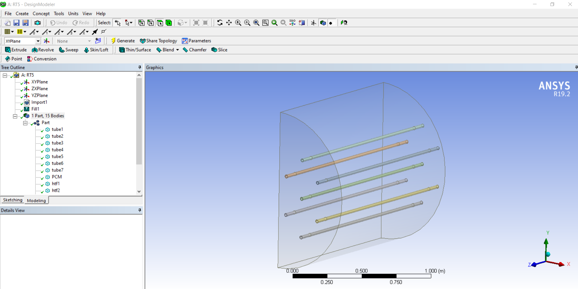
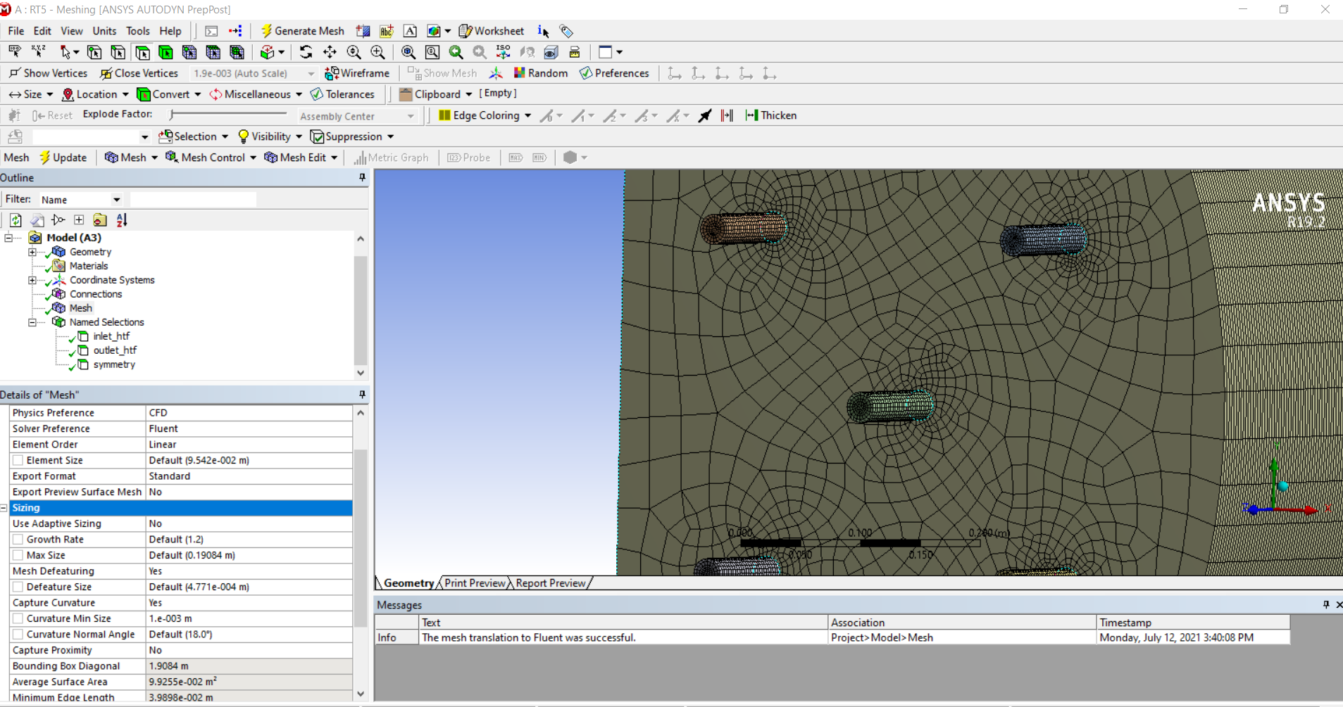
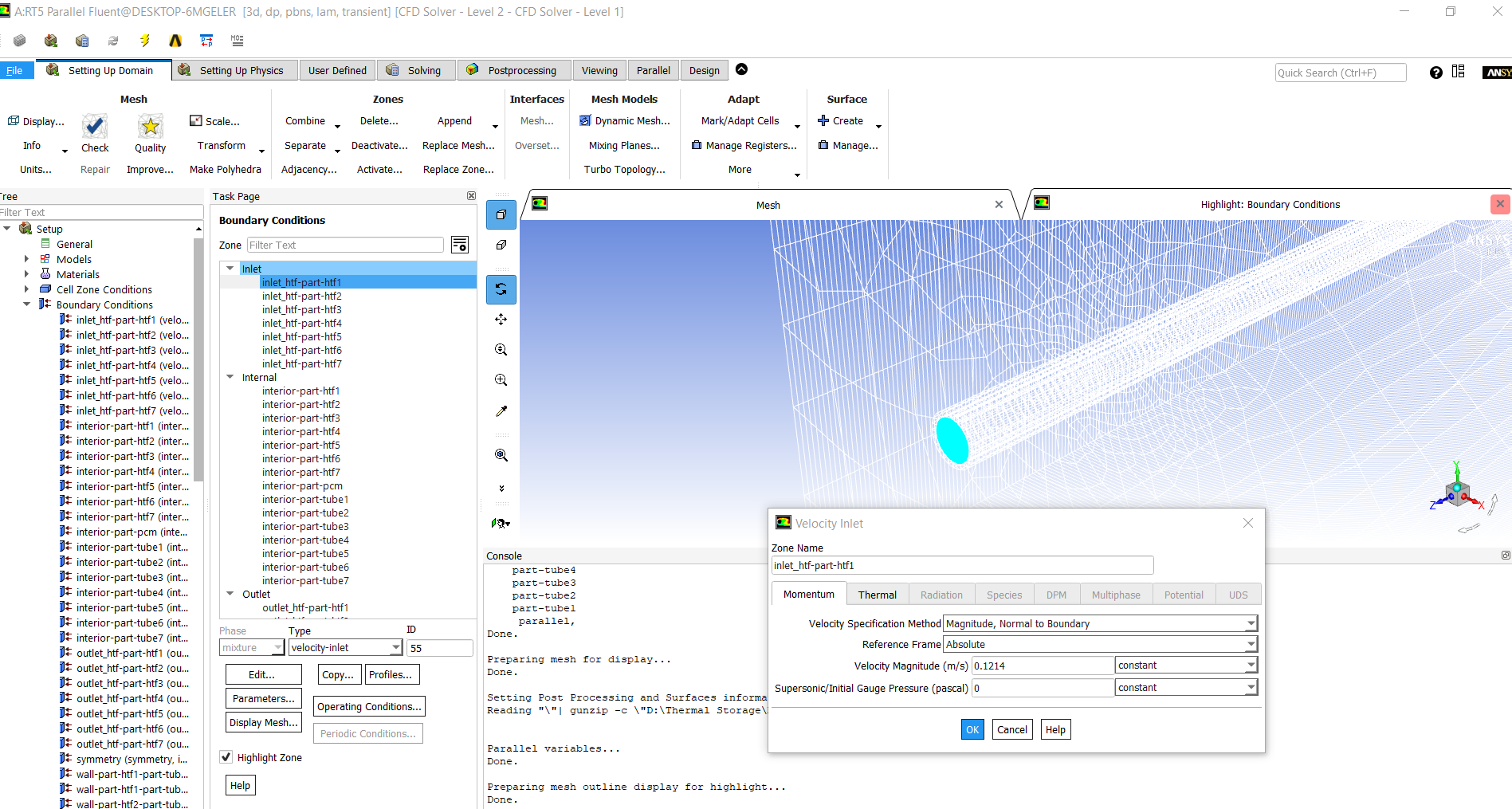
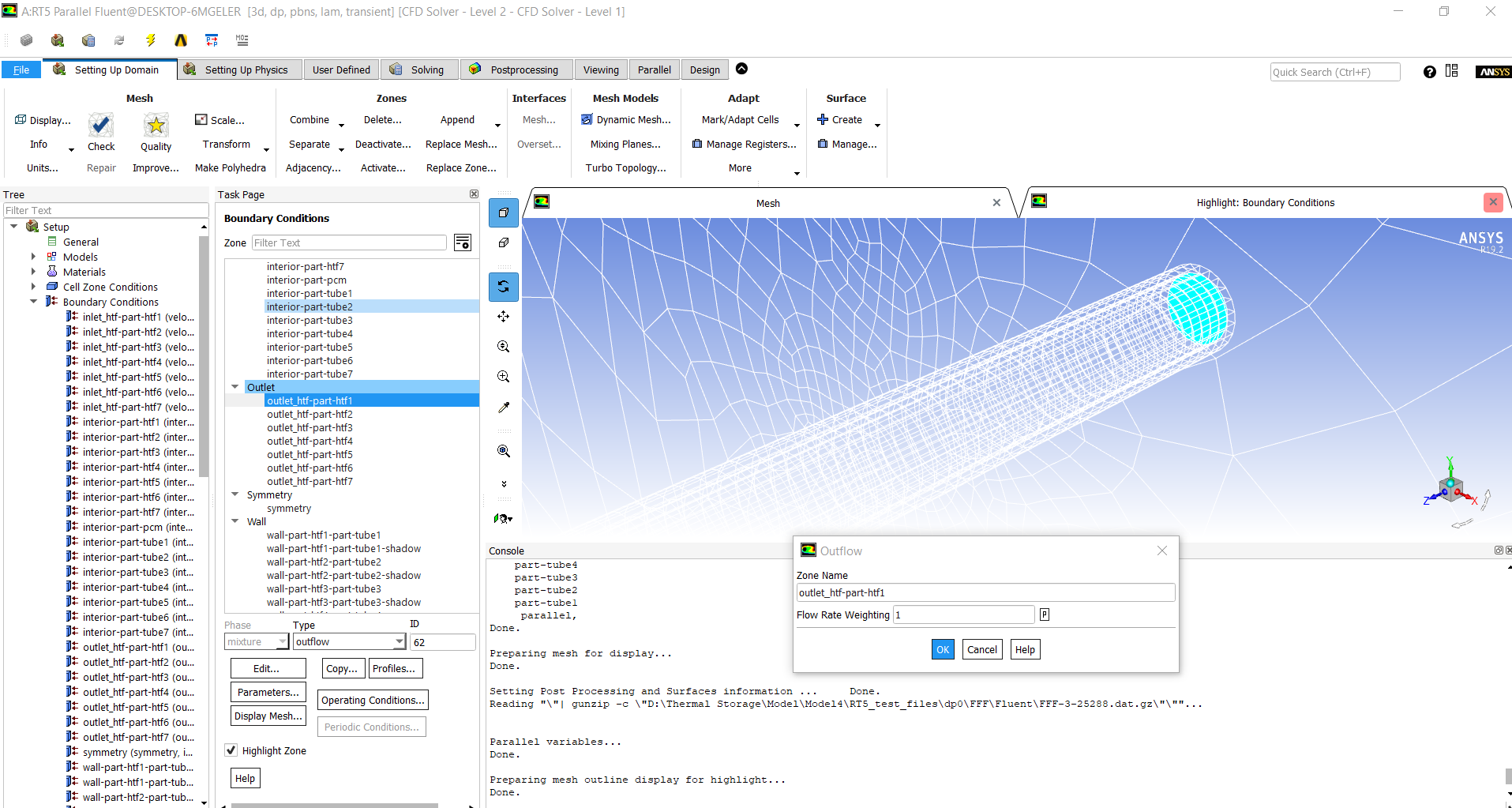
My project is the simulation of a shell and tube heat exchanger with a parrafin. As you can see in picture 1, I have 7 tubes with water flowing inside them, and these tubes are covered from the paraffin. The aim of the simulation is to lower water's temperature and melt the parrafin. I have created the pcm as fluid, the tubes as solid and in addition the water as fluid. In picture 2, you can see the mesh setup I used.As you can see I used linear element order and the default size which may be too small given that the paraffin is 1.2 meters long and has a radius of 1 meter but the tubes have outer diameter of 25.4mm and inner diameter of 20mm. In picture 3, 4, 5 you can see the boundary conditions that I have used. For the water inlet, I use velocity inlet with a velocity of 0.12m/s and a temperature of 40 Celsius. My outlets are modelled as outflows. I have also a symmetry plane. As for the other boundary conditions I have considered the surfaces as walls and I have added a conduction layer in order to have natural convection at the contact of the solid with the fluid. The residuals I have kept them to their default settings. The UDF the same. I have the gravity activated.
At the initialization phase, I choose the whole model to be at 5 Celsius and then I patch the water at 40 Celsius.
I hope this description is helpful. Feel free to make any suggestions you want. I look forward to your answer.
July 27, 2021 at 11:46 amKarthik Remella
AdministratorHello Instead of attaching your images, could you please embed them directly into the post? Ansys employees cannot download images from the forum.
Regarding your question - no, I don't think it makes sense to run a steady-state model and then run a transient model (unless you are changing something in the model after you have your steady-state solution - this is the only way there would be any transient behavior introduced into your model).
Some general suggestions - please reduce the time-step size to ensure proper convergence every single time-step. You might also increase the Max iterations per timestep.
Please share some screenshots so we can provide some specific suggestions.
Karthik
August 28, 2021 at 9:54 amGeorf
SubscriberHi Karthik,
Regarding the transient/steady model, my aim is to run a transient simulation in order to see how the PCM behaves through time. I asked about the steady state in order to make it converge and then continue with the transient. I cannot reduce the time step more because the simulation time is already really long, so I will try making a coarser mesh in order to achieve better results. Do you think this can work?
If I increase the iterations per time step, I should keep the values of the last iterations? What I mean is, if I have 20 iterations per time-step, the values that I need are the ones of the 20th iteration?
Finally I am embedding you the images from the last post. They are shown with the order I have mentioned in the last post. Sorry for any inconvenience and for taking so long to answer.
Thank you a lot,
George.
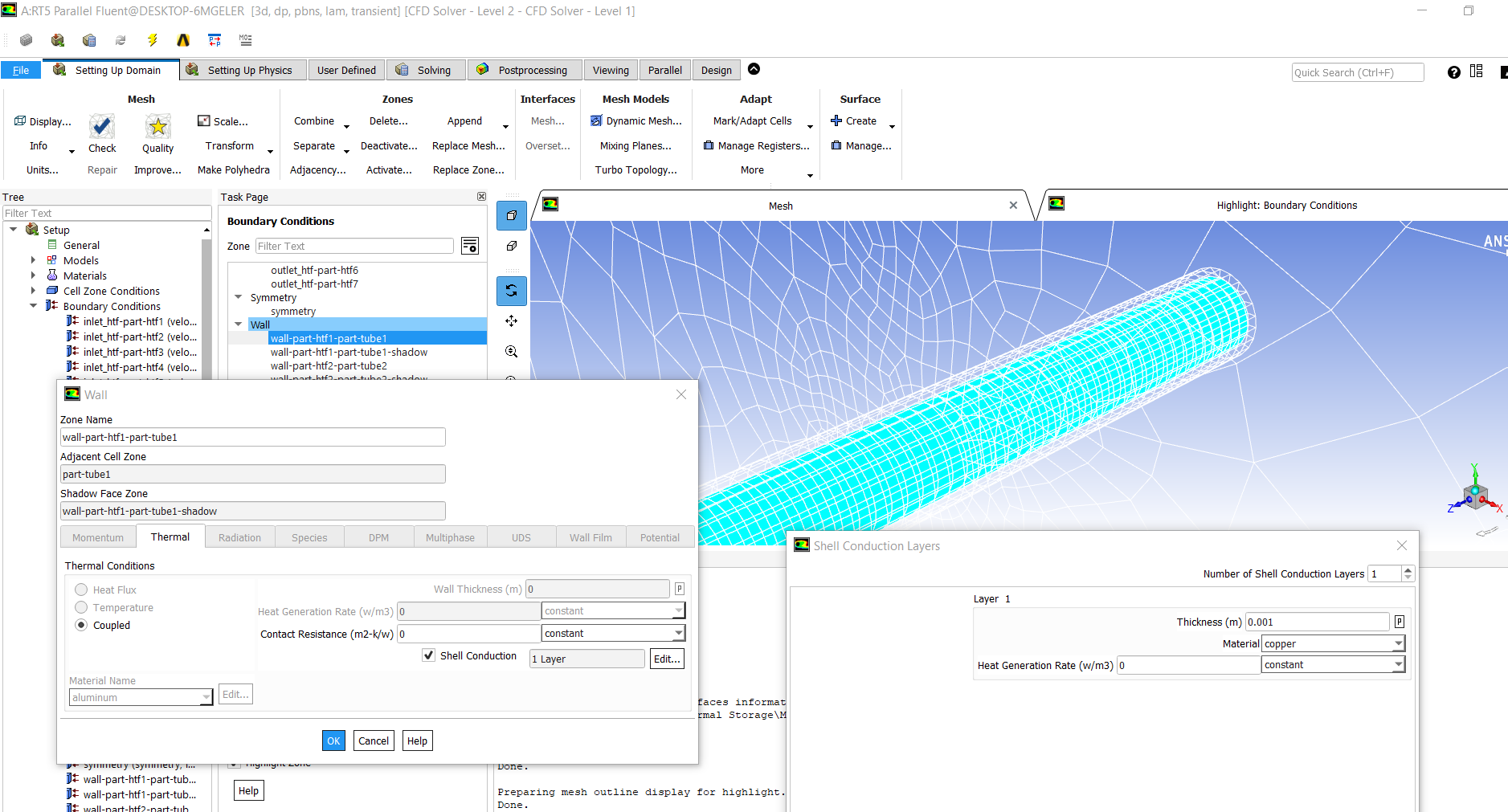
Viewing 8 reply threads- The topic ‘How can I resolve a temperature error in melting of a PCM.’ is closed to new replies.
Ansys Innovation SpaceTrending discussionsTop Contributors-
3557
-
1088
-
1058
-
1045
-
947
Top Rated Tags© 2025 Copyright ANSYS, Inc. All rights reserved.
Ansys does not support the usage of unauthorized Ansys software. Please visit www.ansys.com to obtain an official distribution.
-


