TAGGED: apdl, elastic-strain, integration-point
-
-
May 20, 2024 at 1:37 pm
dhjang4522
SubscriberHi,
Im trying to calculate the nodal stress for a single 10-node tetrahedral element composed of SOLID187, based on nodal displacement using MATLAB.
I first constructed the strain-displacement matrix B based on the shape function formula for 10 node tetrahedron in the ANSYS theory reference.

 Size of B matrix is 6x30, and Nodal displacement is 30x1
 Since shape function of solid 187 is linear, I simply inserted the respective coefficients of shape function into the B matrix
Since these values are from the integration points, I used the ANSYS command ERESX,NO to transfer the values from the integration points to the nodes. According to the reference, solid 187 has 4 integration points. Each vertex receives the value of the integration point directly, and the midpoints are the average of the two nearest integration points' values.
By multiplying the displacement vector with the B matrix, I obtained the strain epsilon and I compared those value to ANSYS. However, the strain values I calculated using MATLAB do not match the strain values obtained from ANSYS.
I suspect that the error might be due to an incorrect calculation of the B matrix, or perhaps the data at each vertex in ANSYS does not actually match the values at the integration points exactly. I have followed the node ordering exactly as it is presented in the ANSYS reference.
Could you please help me understand if there is a mistake or misunderstanding in my approach?
-
May 29, 2024 at 2:48 pm
Mike Rife
Ansys EmployeeHi C Deho
I don't think there is a mistake in your approach; and I don't have MatLab so really helping is a little out of the question. Can I instead change course and point you here:
https://mapdl.docs.pyansys.com/version/stable/examples/gallery_examples/03-general-fea/00-how_finite_element_works.html#sphx-glr-examples-gallery-examples-03-general-fea-00-how-finite-element-works-py
It's an example from a popular FEA textbook that compares the Mechanical APDL version of a plane quadratic element to one written from scratch using Python and NumPy. Perhaps you could practice with this and implement it in MatLab as well. Then if all goes well move onto the tetrahedral element.
Mike
-
May 30, 2024 at 9:05 am
dhjang4522
SubscriberHi Mike,
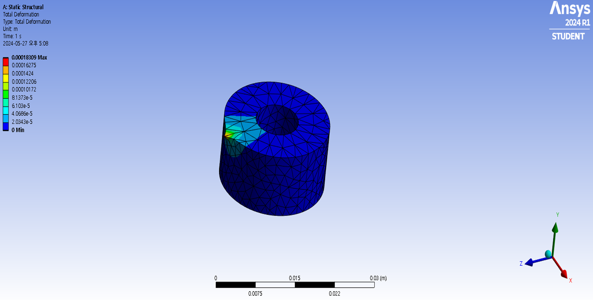
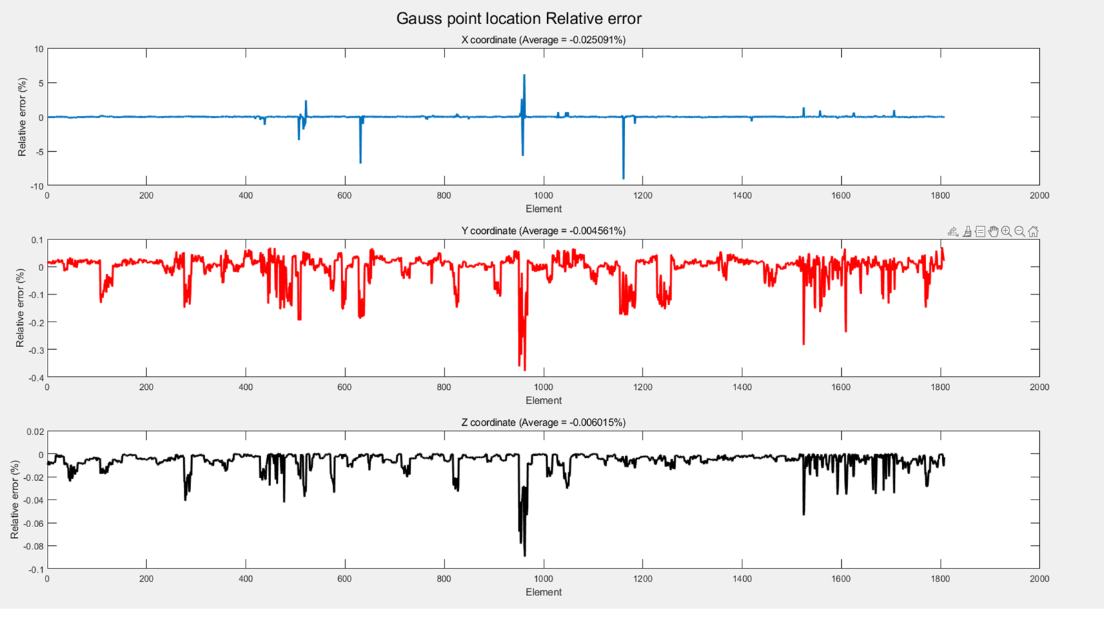
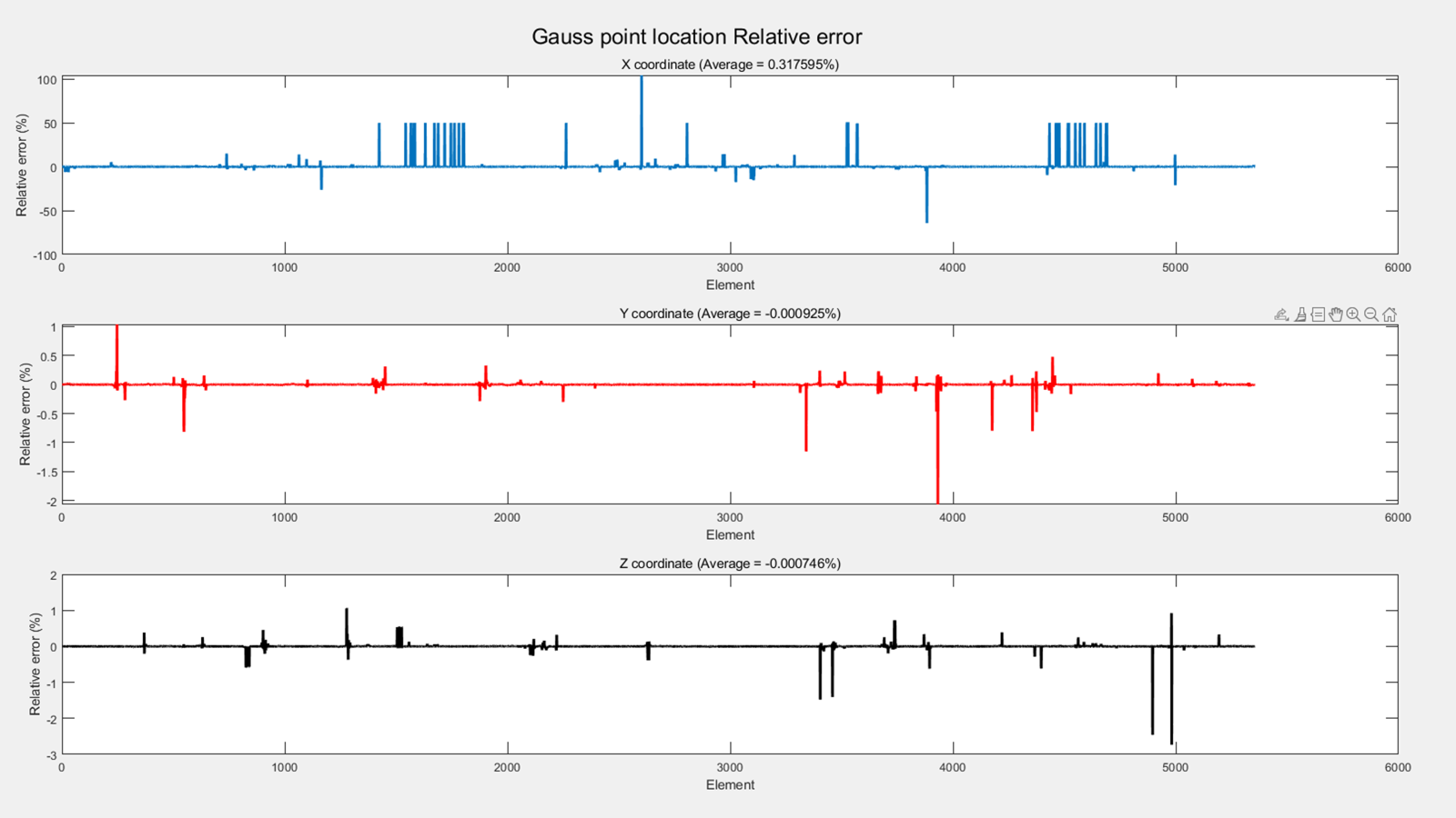
Thank you for your reply. I've recently completed a code to calculate strain over the last week. When dealing with a single element or simple model geometries (such as a Ring or a basic cube), the strain results match very well with those from MATLAB. However, as the complexity of the geometry increases, the error in strain at each node becomes larger. To investigate the potential issue, I checked the integration points of each element. The Y and Z direction coordinates match well regardless of the geometry, but there are significant discrepancies in the X direction coordinates for some elements as the geometry becomes more complex (with some points showing up to a 10000% difference).
Model 1
Model 2
Model 3
It seems link you've provided do not contain an explanation for this aspect.
Is there an option within ANSYS to adjust the location of Gauss points based on the geometry? Why would the error be more pronounced in the X direction?
-
-
May 30, 2024 at 5:31 pm
Mike Rife
Ansys EmployeeOn your 'hand calc' version did you change the differential (d/dx) to go from global to local coordinates?
And I don't have access to MatLab so I cannot say why the results from MatLab are wrong.
-
June 4, 2024 at 2:03 pm
dhjang4522
SubscriberI have applied the same code to all models. My question is not about the code but rather whether, within ANSYS, the location of Gauss points changes for more complex geometries ( results match well for simple models regardless of the number of nodes and elements, I believe there is no issue with the code).
There are discrepancy at both Gauss point locations and strain values. The Gauss points are derived using shape functions, and the strain-displacement matrix B, which is used to calculate strain, is obtained by differentiating these shape functions. Therefore, I suspect that the primary source of discrepancy lies in the Gauss point locations.
Is there an option within ANSYS to disable such automatic adjustments to the Gauss point positions or shape functions? Or, if you have any insights or suggestions on how to address this issue, I would greatly appreciate your advice.
-
-
- The topic ‘How can I calculate strain at integration point?’ is closed to new replies.


-
4778
-
1565
-
1386
-
1242
-
1021

© 2026 Copyright ANSYS, Inc. All rights reserved.


