-
-
December 19, 2021 at 8:31 am
chobanzadeh
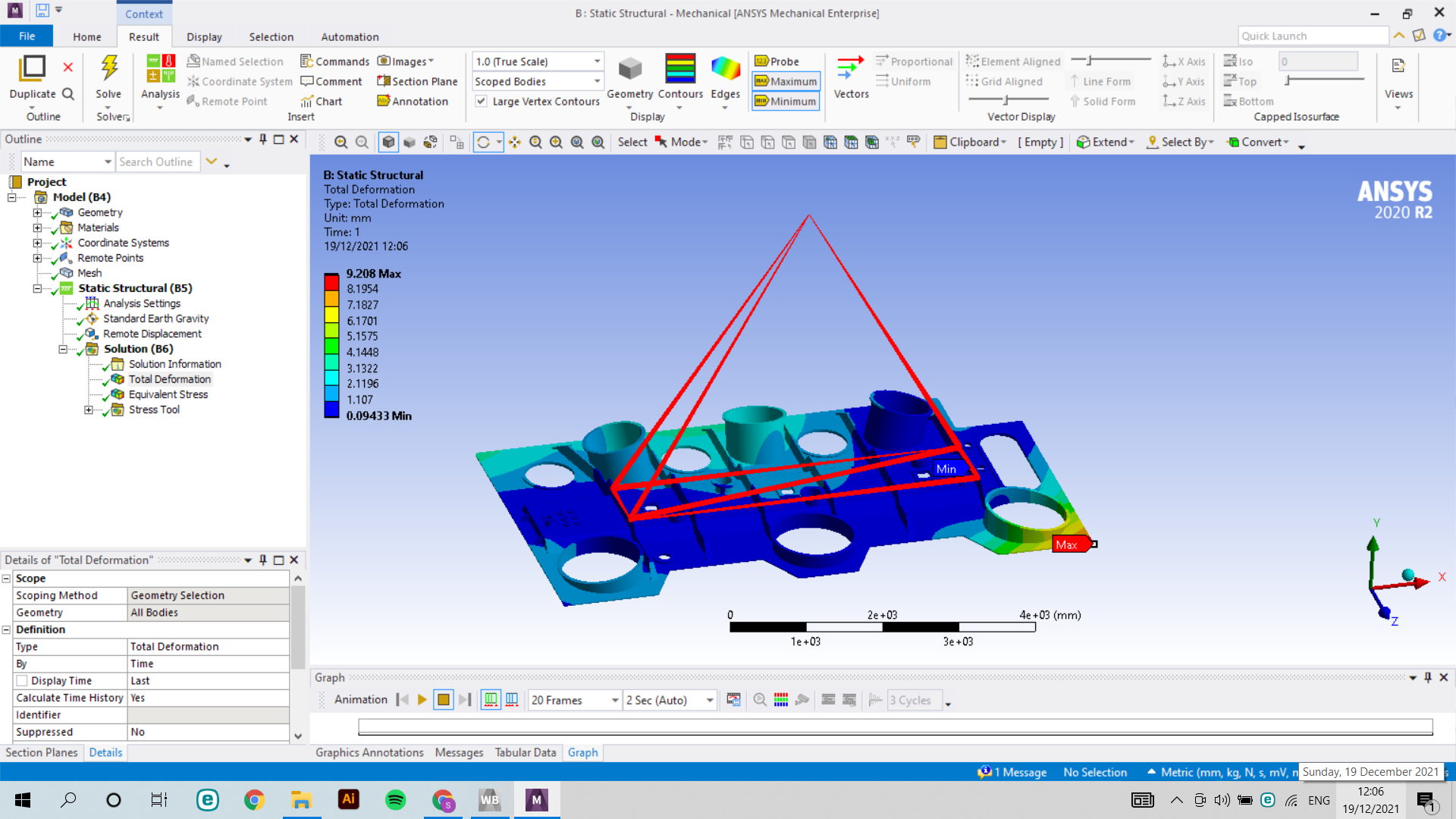
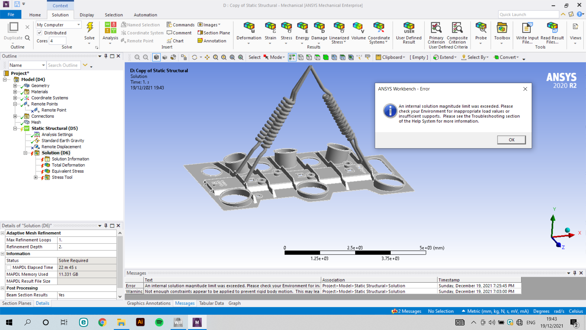
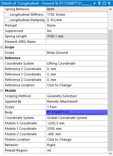
SubscriberI created a coordinate system with the faces of lifting holes, on the coordinate where my Hook will stand after I added the Remote point again with these lifting holes and the new coordinate system. After I added remote displacement and chose this remote point, I constrained every axis. I have chosen beams: on and visible on results: yes. but I didn't get the results I expected, and also as you can see from the photo, beams are not only connecting lifting holes to the remote point, they also connect lifting holes with one another. Why this is even happening, I don't understand
December 19, 2021 at 1:14 pmpeteroznewman
SubscriberBelow is a link to a relevant discussion on this site.
/forum/discussion/3790/a-tutorial-for-creating-and-analyzing-cables
Come back if you have any questions.
December 19, 2021 at 3:57 pmDecember 19, 2021 at 5:43 pmpeteroznewman
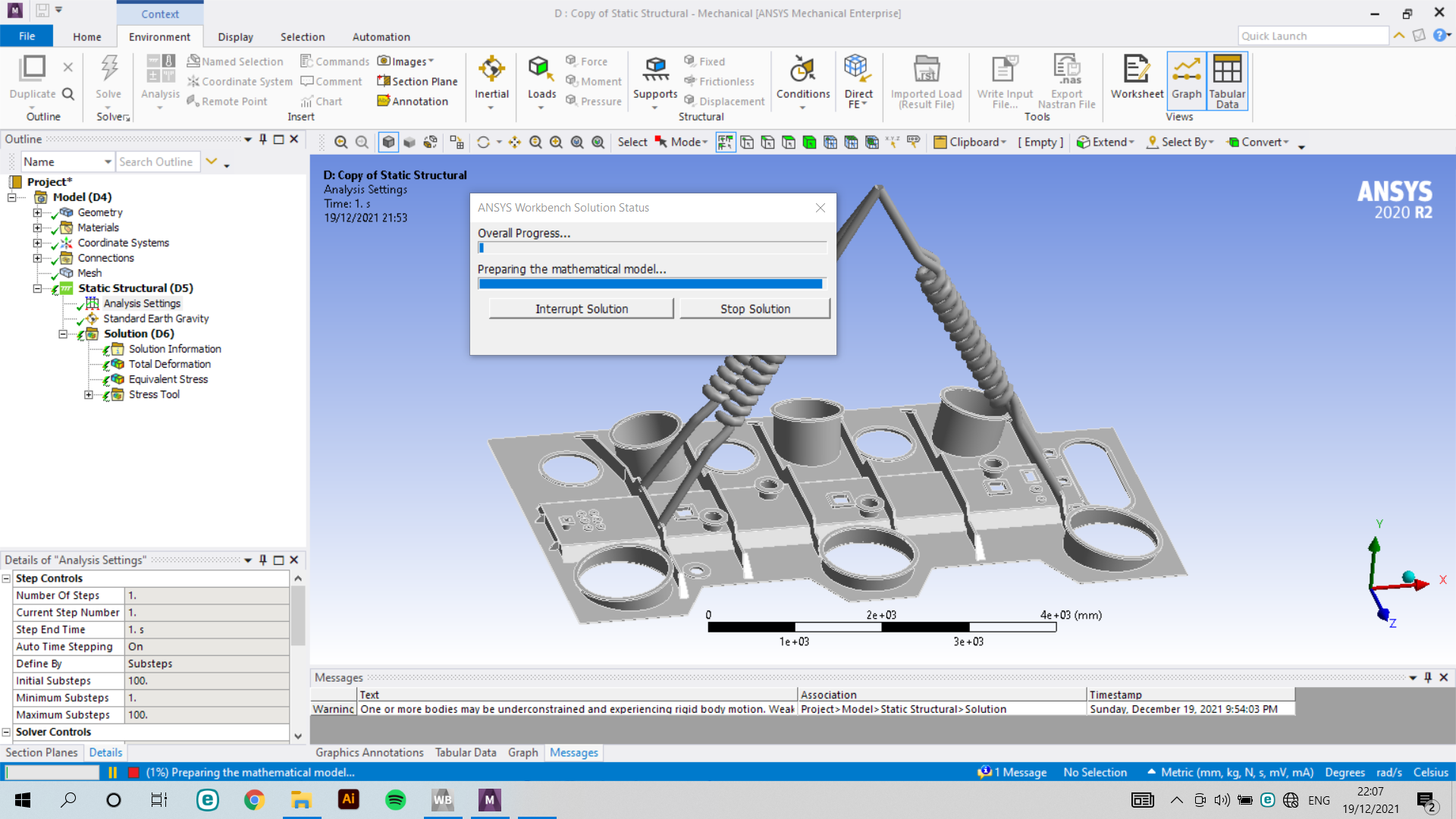
SubscriberUnder Analysis Settings...
Turn on Weak Springs and try that first. If that doesn't work, apply the following...
Turn on Large Deflection
Turn on Auto Time stepping
Set Initial Substeps to 100, Minimum Substeps to 1, Maximum Substeps to 1000
December 19, 2021 at 6:31 pmDecember 19, 2021 at 8:18 pmpeteroznewman
SubscriberWhat is the weight of the part you are suspending?
What stiffness did you specify for the springs?
What direction is Gravity pointing?
December 19, 2021 at 8:31 pmchobanzadeh
SubscriberThe weight of the part is 3970 kg.
Actually, I didn't know the stiffness so used the one in the example, converted it to N/mm, 1750N/mm.
The direction of gravity is -Y.
December 19, 2021 at 9:16 pmpeteroznewman
SubscriberThe mass of the part is 3970 kg, the weight is 38,932 N.
Divide that by 4 to assign the lift force for each spring = 9,733 N
The angle of the spring causes the tension in the spring to be higher than the lift force, so would be 11,240 N for 30 degrees off vertical.
So each spring might stretch about 6.4 mm, which may be okay for a part that is over 4000 mm long, but it might help if you double or triple the stiffness of the springs.
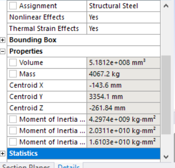
Do you know the X and Z coordinates of the Centroid of the Solid? Click on the Solid under Geometry branch of the Outline look them up in the Details window under Properties.
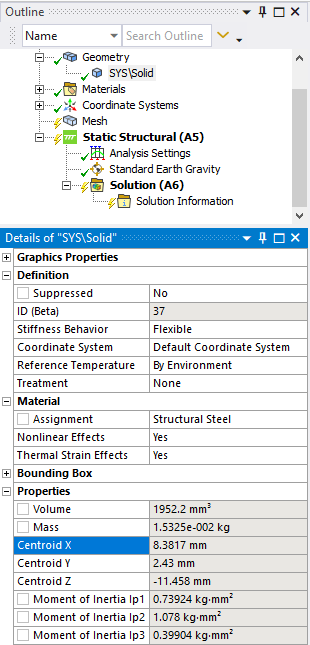 The ends of the spring must be at the same X and Z coordinates as the Centroid of the mass, otherwise the part will want to rotate as it is lifted. Obviously, the Y coordinate of the springs is much larger.
December 19, 2021 at 9:43 pmDecember 19, 2021 at 11:10 pmpeteroznewman
SubscriberThe part to be lifted has a Center of Mass (Centroid) at X = -143 mm and Z = -262 mm.
This is where the Lifting Coordinate origin should be, since the springs end at that origin (0,0,0).
Change the Lifting Coordinate Origin to Global Coordinates, and type the values above, then try to solve.
Set the Preload on each spring to 11,240 N.
-
June 23, 2023 at 10:45 am
Steven Miller
SubscriberHi,
I have a similar lifting problem that I am analysing using springs as the lifting slings. I am applying factored loads to simulate the payload in the frame to a DNV standard. Is it best to apply the preload in the springs first then apply the factored load using a multi-step analysis?
Viewing 9 reply threads- The topic ‘How can I analyze the lifting process with ANSYS? 4 lifting holes are provided.’ is closed to new replies.
Innovation SpaceTrending discussions- LPBF Simulation of dissimilar materials in ANSYS mechanical (Thermal Transient)
- Real Life Example of a non-symmetric eigenvalue problem
- How can the results of Pressures and Motions for all elements be obtained?
- BackGround Color
- Contact stiffness too big
- Element Birth and Death
- Python-Script to Export all Children of a Solution Tree
- Which equations and in what form are valid for defining excitations?
Top Contributors-
4592
-
1494
-
1386
-
1209
-
1021
Top Rated Tags© 2025 Copyright ANSYS, Inc. All rights reserved.
Ansys does not support the usage of unauthorized Ansys software. Please visit www.ansys.com to obtain an official distribution.
-


Ansys Assistant

Welcome to Ansys Assistant!
An AI-based virtual assistant for active Ansys Academic Customers. Please login using your university issued email address.
Hey there, you are quite inquisitive! You have hit your hourly question limit. Please retry after '10' minutes. For questions, please reach out to ansyslearn@ansys.com.
RETRY
