TAGGED: ansys-fluent, heat-flux, udf
-
-
November 1, 2023 at 12:48 am
MengFan Tseng
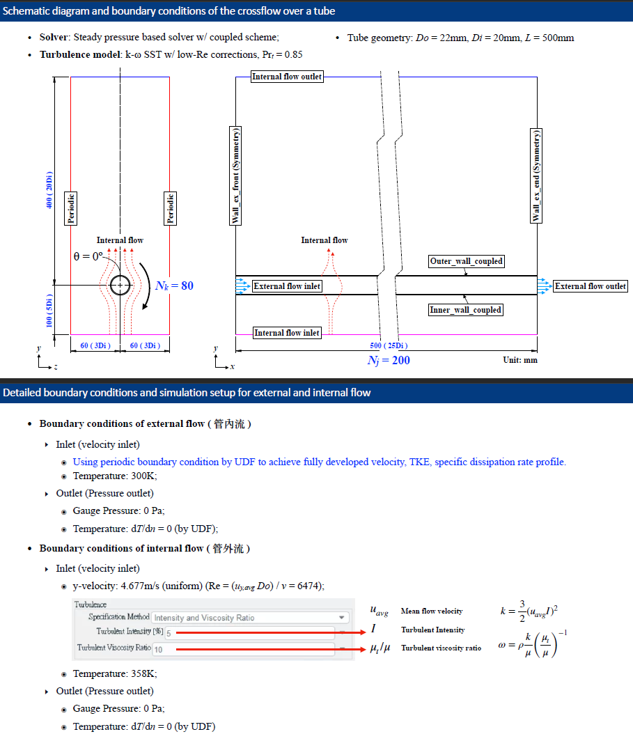
SubscriberHi all, I am currently working on a simulatoin case of "crossflow over a tube", the shematic geometry and boundary conditions are shown in following figure

- Introduction -
I've develpoed a mathematical model ( in-house code ) to simulate the heat transfer of the tube solid region including external flow ( see above figure ) and aim to couple it with Ansys Fluent. The in-house code require the outer wall heat flux from Ansys Fluent as the boundary conditions.
- How I calculate the outer wall heat flux using UDF -
The whole process is control by DEFINE_ON_DEMAND ( a macro in UDF ) which is a general-purpose macro in Ansys Fluent. I calculate the outer wall heat flux as below:
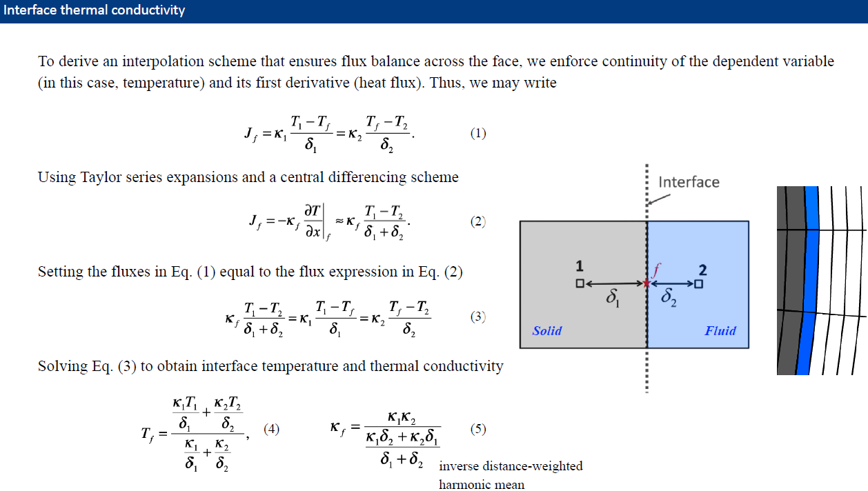
Using right hand side of Eq. (1) in above figure, the snippet of code// Phase domain Domain *domain = Get_Domain(1) ; // The ID of the BC created in ANSYS Fluent const int wall_ID = 21 ; // Get the thread from the domain, the thread is partitioned Thread *f_thread = Lookup_Thread( domain, wall_ID ) ; // Create face ID face_t f_ID ; /* Adjacent cell information */ // adjacent cell index of the boundary face cell_t c0 ; // thread index of adjacent cell Thread *t0 ; // xf represents facets location array and xc is cell center locatoin array real xf[ND_ND] ; real xc[ND_ND] ; begin_f_loop( f_ID, f_thread ) { /* Get the cell center F_CENTROID( xf, f_ID, f_thread ) ; /* Get the cell id of the cell adjacent to the face*/ c0 = F_C0( f_ID, f_thread ) ; /* Get the Thread id of the cells adjacent to the face*/ t0 = F_C0_THREAD( f_ID, f_thread ) ; C_CENTROID( xc, c0, t0 ) ; /* dx is ignored because the cell center and face center are align in radial direction double dy = abs(xc[1] - xf[1]) ; double dz = abs(xc[2] - xf[2]) ; double dr = sqrt(dy*dy+dz*dz) ; // Calculate the surface heat flux, k_f * (T_cell - T_face ) / dr q_array[ f_ID ] = C_K_L(c0, t0) * (C_T(c0, t0) - F_T(f_ID, f_thread)) / dr ; // C_K_L(c0, t0) is the UDF macro return fluid thermal conductivity } end_f_loop( f_ID, f_thread )
- Main Issue -
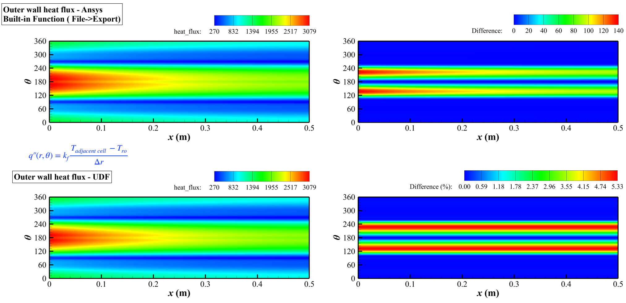
The difference between the outer wall heat flux calcuted by UDF and from Ansys ( using built-in function on GUI, File->export->solution data->Total Surface Heat Flux ) are shown below
The outer wall heat flux is represented in 2D and θ=180° is bottom region of the tube. Refer to the figure, most of the error occurs at θ=120°~240° and the maximum error of 5.33%.
Does anyone have any experience with this? I would appreciate your advice and suggestions. -
November 6, 2023 at 1:11 pm
SRP
Ansys EmployeeHi,
Ensure that the mesh resolution is appropriate, especially in the regions of interest (θ=120°~240°). Grid quality and resolution can significantly impact the accuracy of your simulation. You may need to refine the mesh in these areas to capture the flow and heat transfer more accurately. Ensure that the boundary layer is well-resolved near the tube wall. The discrepancies in heat transfer can often be related to insufficient resolution of the boundary layer. You may need to refine the mesh near the tube wall and apply an appropriate turbulence model to capture the boundary layer accurately.
Thank you.
-
- The topic ‘How Ansys Fluent Calculate the Wall Heat Flux?’ is closed to new replies.


-
4959
-
1639
-
1386
-
1242
-
1021

© 2026 Copyright ANSYS, Inc. All rights reserved.


