-
-
October 16, 2017 at 10:11 pm
Mannil
SubscriberHi, I am new to ANSYS and I'm wondering if there is a simple way to simulate an aluminium honeycomb structure, without actually creating the geometry. I'm gonna have sandwich plate thats like 400x250 and SolidWorks just crashed when I tried to make a pattern om tiny honeycomb cells.Â
And also if there is a simple way I can specify the strength between bonded contacts instead of actually CADing epoxy adhesives.
Â
ThanksÂ
-
October 22, 2017 at 5:17 pm
peteroznewman
SubscriberYes, there is a simple way to model honeycomb sandwich panels in ANSYS. Honeycomb behaves as an orthotropic material, which means the properties change with the direction through the material. You can create an orthotropic material model in ANSYS for the honeycomb core that looks like this.
Note that honeycomb core is stiffer in shear in the L direction than the W direction, so you have to use a coordinate system in ANSYS to orient the material the way you want to for your application.
The material for the aluminum face sheets would be like the aluminum that is included in the materials database, which is an isotropic elastic material.
In CAD, you create a solid body with the thickness of the honeycomb core and the outline of the shape of the panel you are using. The top and bottom face sheets that bond to the honeycomb core can be created as either solid bodies or as sheet bodies. This is a very lightweight representation of the honeycomb sandwich since you don't model the individual cells. Those are represented by the material property assigned to the solid body that encloses the volume of the honeycomb core.
If you create the face sheets as solid bodies, you will have three bodies for the sandwich structure. In DesignModeler, select those three parts and Form New Part to create a single part with three bodies. When you mesh in Mechanical, common nodes at the coincident surfaces will hold each face sheet to each side of the core thickness. These three bodies should be sweepable so you will have an efficient hex mesh to represent the sandwich (not a tet mesh). Make sure you have two or more elements through the thickness of each solid body.
Well made aluminum honeycomb sandwich should fail in the core itself, and not by the epoxy failing. Therefore you don't need to include the epoxy in the model as it is stronger than the aluminum honeycomb core. Vendors of honeycomb core publish the strength of the core. The table below shows the values of shear strength that can be compared with the shear stress computed in the ANSYS model to determine if a failure is predicted for that load.Â
Note that if you have a much lower stress than the strength shown above, but the stress cycles between zero and positive stress or negative and positive stress values, the core can exhibit a fatigue failure. Unfortunately, manufacturers rarely publish fatigue strength values or S-N fatigue curves, so you would have to do your own fatigue testing if cyclic loading is expected.
-
August 20, 2018 at 9:34 pm
AchilleasMil
SubscriberHi,
I see you have experience with sandwich modelling. I am currently studying a sandwich plate for a university course project which has two laminated facesheets and I have the following question, do you have a suggestion on how to get/plot the interlaminar stresses of the laminate and the stresses of the adhesive between the aluminium honeycomb core and the facesheets?
For the intelaminar stresses of the laminate I saw that the ACP feature offers one option but couldn't quite handle it.
Thanks in advance!
Â
Â
-
August 21, 2018 at 4:03 am
peteroznewman
SubscriberHi Achilleas,
I have not used ACP, so I don't know either.
You have two sheets laminated together with an adhesive to make a facesheet. Model all three layers with solid elements and use Shared Topology to have the three solids share common nodes at the two interfaces between sheet and adhesive, then you will have a layer of adhesive that you can plot the interlaminar stresses on directly.
The stresses in the adhesive between the honeycomb core and the facesheet is more complicated, since the geometry is so complex. A well designed and properly manufactured honeycomb sandwich has the core as the weakest component in the sandwich. The adhesive is stronger than the core, so you don't really need to study the stresses in the adhesive, only the core. The study of stresses in the core is not at a detailed level of the individual cell, but at a bulk level as I was showing above.
Regards,
Peter
-
August 21, 2018 at 10:59 am
Sandeep Medikonda
Ansys EmployeeHi Achilleas,
 When you say, ACP 'couldn't quite handle it', can you please elaborate a little? Are you seeing any specific error messages? Pictures will help understand better.
P.S: If you have a new question, please post a new discussion to get better help in the future.
Regards,
Sandeep
-
August 23, 2018 at 8:33 pm
AchilleasMil
SubscriberThanks a lot for your answers!
I have already made a sandwich model of the explicit geometry of honeycomb with shell elements and have shared topology between the facesheets wich are also made of shell elements.
The thing is that I couldn't find a tutorial of how excactly to get the best layup setup in order to get the interlaminar stresses between plies. I am using the Epoxy Carbon Woven Wet material which is offered in the material library of ansys, so the epoxy resin is supposed to be already considered in my layup..should I just set an extra ply of pure epoxy between each of the plies I already have, and then choose the interlaminar stresses output which I see in the Create Stress tab of the Solution in ACP Post?
Untill now when I choose the interlaminar normal stresses option I get the same results as with when I don't choose it, for each woven wet ply.
I didn't use solids since I can't import solid elements in ACP I get the : input validation error : there is no data contained in the input mesh file. Although I have alredy meshed my model.
I want also to do a basic thermal analysis afterwards and see the temperature distribution in the plies. With shell elements I cannot, I think it is only for solids, right?
So maybe it would be better to do a model of solids but firstly I can't import solids in ACP and secondly I don't know which is more correct since honeycomb is really thin (0,025 mm) and also my facesheets have a thickness of 1 mm each, where the core has a thickness/height in Z direction of 20 mm.
Can you help me?
-
August 24, 2018 at 1:36 am
peteroznewman
SubscriberAchilleas,
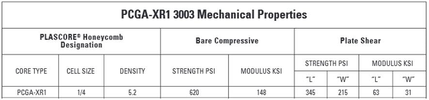
If you purchase honeycomb core from a manufacturer, they have done the experimental work to measure the shear modulus of the core in two directions: the ribbon direction (L) and transverse to the ribbon (W). They also measure the compressive modulus in the 20 mm thickness (T) direction. You can see those values in the table in the first post in this discussion.
Once you have those three modulus values, and also the strength values in those three directions, you are ready to use that data in an orthotropic material model. That means you create a solid model, 20 mm thick, and assign the orthotropic material to that solid. You have to make sure a coordinate system has its X, Y, Z directions pointing in directions that correspond to the thickness, ribbon and transverse directions of the modulus values entered in Engineering Data.
Now you also have to share topology with some facesheets that might have it's own orthotropic material constants if it is a composite layup, or it could be an isotropic material if it is aluminum facesheet.
It sounds like you have actual honeycomb foil geometry, like is shown in the image above. Does it have double thickness of foil as shown in that image? When core material is tested to obtain the shear modulus, it is bonded to 20 mm thick face plates. That is because the only flexing that is supposed to occur is in the core. Here is the test apparatus from ASTM C273 -11 Standard Test Method for Shear Properties of Sandwich Core Material.
If you want to simulate the experimental measurement of core shear modulus, you can simply make one face of the core (all the honeycomb edges) be a fixed support and the other face of the core (all the edges) have a remote force, with a Rigid behavior, to pull the core sideways.
Shell elements and beam elements can conduct and convect heat just as well as solid elements, so don't rule shell models out just because you want to do a thermal model.
As I said, I'm not an ACP user, so someone else can comment on that. I will say that I have made models that use carbon fiber sheets. I have them measured to obtain the orthotropic properties so my models flex the way the real part will flex, but I am not interested in interlaminar stresses.
 Regards,
Peter
-
August 24, 2018 at 11:09 am
AchilleasMil
SubscriberÂ
Dear peter oz newman, thanks a lot for your advice about the homogenization assumption to form the solid core element. When I do that while having my facesheets as shell elements the program doesn't let me share topology between shells and solids, so I have to use bonded contacts.
I am thinking about using only solids in the thermal analysis I want to do using ACP. But I am also curious if in the static analysis of the model with the solid elements I will get the same results as in the static analysis of the model with the shell elements. I would do both of them to check the difference in the result, but as I said I have problems with importing solids in ACP.
Dear Sandeem Medikonda, thanks also about your answer, could you please help me with the questions about the ACP I posted in my former answer?
Hi Achilleas,
 When you say, ACP 'couldn't quite handle it', can you please elaborate a little? Are you seeing any specific error messages? Pictures will help understand better.
P.S: If you have a new question, please post a new discussion to get better help in the future.
Regards,
Sandeep
-
August 24, 2018 at 11:49 am
peteroznewman
SubscriberDear Achilleas,
When I was building models of honeycomb sandwich, I built two models, one with shells bonded to a solid core, and one with three solids using shared topology.
They gave different deformations for the same load.
I don't recall what formulation of Bonded contact was used, but I did an experiment to measure the deflection under 2000 lb load during a quarter-point bending test and had a shell model where I adjusted the shear modulus of the core until the FEA model matched the experimental data.
Below is a plot of the experimental Force-Deflection data for three samples cut along the ribbon L direction, and the slope I fitted to the data. Another plot had three samples cut along the W direction, which had a lower slope.
Below is the FEA model, which used symmetry to model one half.
I used Parameter Set feature of Workbench to plot this curve to look up the experimental deflection under the 2000 lb load to see what the shear modulus should be for that material direction, L or W.
In this way, I knew my model accurately matched the experimental data.
Regards,
Peter
Â
Â
-
January 1, 2019 at 4:12 pm
Sandeep Medikonda
Ansys Employeeplease open a new discussion and reference to this one using the #Permalink
This discussion has been closed.
Please take a moment to refer to the Guidelines on the Student Community
-
August 23, 2020 at 12:29 pm
KnHw
SubscribernHello, ni am trying to simulate a Honeycomb Cylinder. Therefore i have to set up my material data. I tried to do it like explained in this Post. I managed evertything except the E-Modulus in the two not compressive directions. Is it possible to calculate them trough the density of the core compared to the of the solid material? I found some literatur where the Shear-Modulus is calculated with this formula G_c=G_s*(rho_c/rho_s)^1,5. It is possible for you to tell me wich Alloy and wich core geometry you used in this post.ns=solidnc=corennThanksn -
August 23, 2020 at 12:51 pm
peteroznewman
Subscriber,all aluminum alloys have about the same modulus. It is the strength that varies by a lot between different alloys and heat treatments.nEstimating the core shear modulus from the density ratio seems like a reasonable approach.n -
August 24, 2020 at 6:58 am
KnHw
Subscribernthanks for your fast response. For the Y-Modulus i will use also some proprtional factor wich depends on the density.n
-
- The topic ‘Honeycomb structure, adhesive contact’ is closed to new replies.
- At least one body has been found to have only 1 element in at least 2 directions
- Script Error Code:800a000d
- Element has excessive thickness change, distortion, is turning inside out
- Elastic limit load, Elastic-plastic limit load
- Image to file in Mechanical is bugged and does not show text
- Help to do quasistatic analysis in static structural module
-
1932
-
823
-
599
-
591
-
366
© 2025 Copyright ANSYS, Inc. All rights reserved.