-
-
April 27, 2024 at 8:34 pm
Dhanush Kumar K K
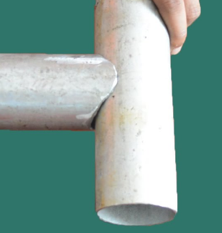
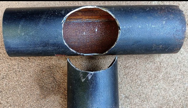
SubscriberWhats the best way to simulate a drop test of a landing skid part which uses T joints as shown below. The pipes will have a weld around it's edges and I need to test a couple of configurations like below 1,2 where on has a cutout and other without a circular cutout.
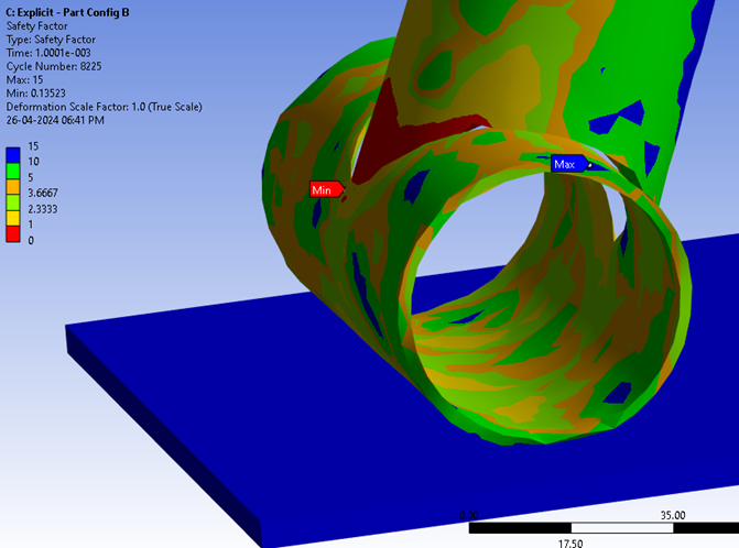
I have modelled the two pipes as separate bodies and applied bonded joint connections, defined a weld mesh around their edges and did a explicit analysis by applying a initial velocity condition to hit a fxed plate on bottom (image 3). Is this a correct way to test the strength of the joints or should I model a weld separately ? The max VM stress and deformation was somewhat similar for both cases; As my focus is to only understand the presence of cutout in primary pipe, how should I change my simulation to get good comparision. Thank You.


-
April 28, 2024 at 10:30 am
peteroznewman
SubscriberAvoid bonded contact in regions of high stress gradient and potential plastic deformation. Construct the weld bead solid in SpaceClaim and use Shared Topology to connect the mesh or simply unite the solid bodies into a single solid body for meshing. The stress results will be more accurate from this mesh than with separate meshes and bonded contact.
-
- The topic ‘Hollow section connections Joint Analysis’ is closed to new replies.


-
4633
-
1535
-
1386
-
1225
-
1021

© 2025 Copyright ANSYS, Inc. All rights reserved.


