-
-
June 19, 2023 at 10:10 pm
wancheng gao
SubscriberHello Community,
I was simulating cracks near bolt holes using Cohesive zone model (pure penalty formulation) to define the debonding.
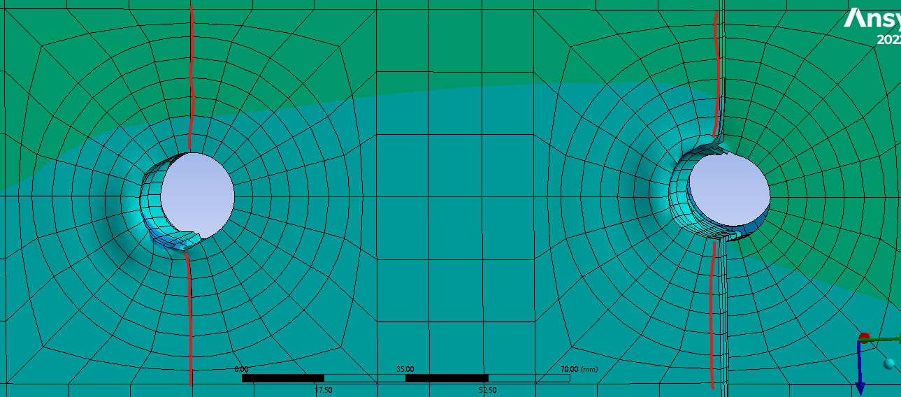
As shown in Fig.1, i always saw the elements near the bolt hole were highly distored due to stress concentration. They were smooth at the beginning. THe red lines are the predefined cracks using CZM material.
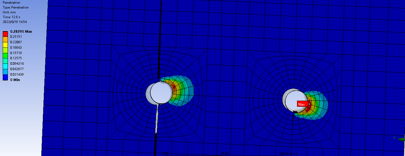
As shown in Fig.2, the frictional contact between bolt and its surrounding material was created. I also figured a great amount of penetration there.
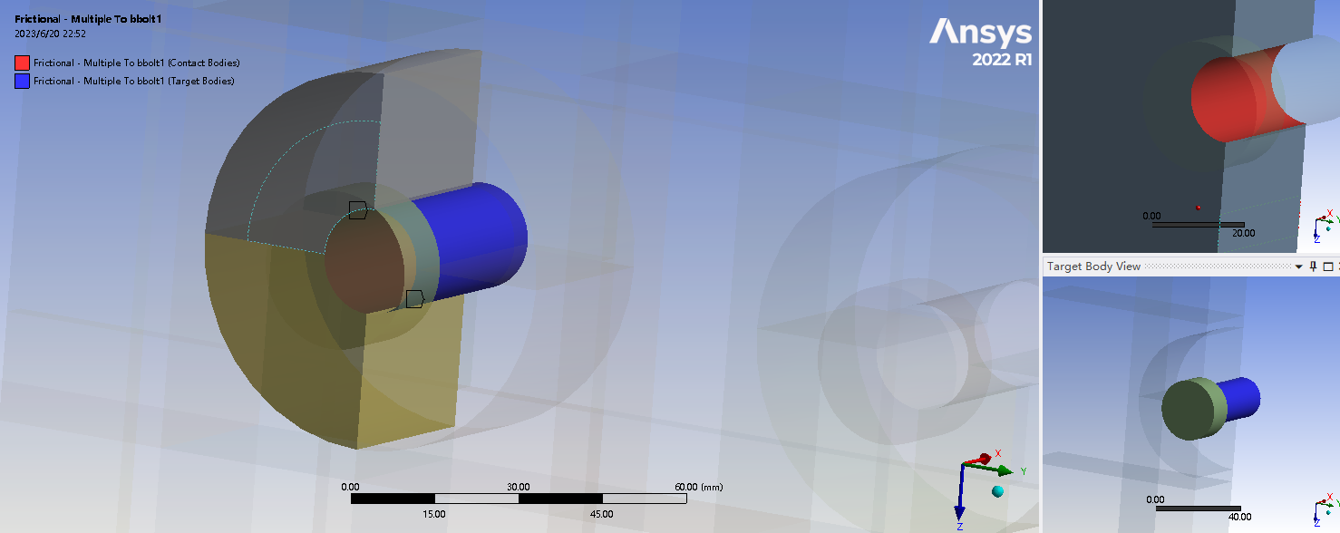
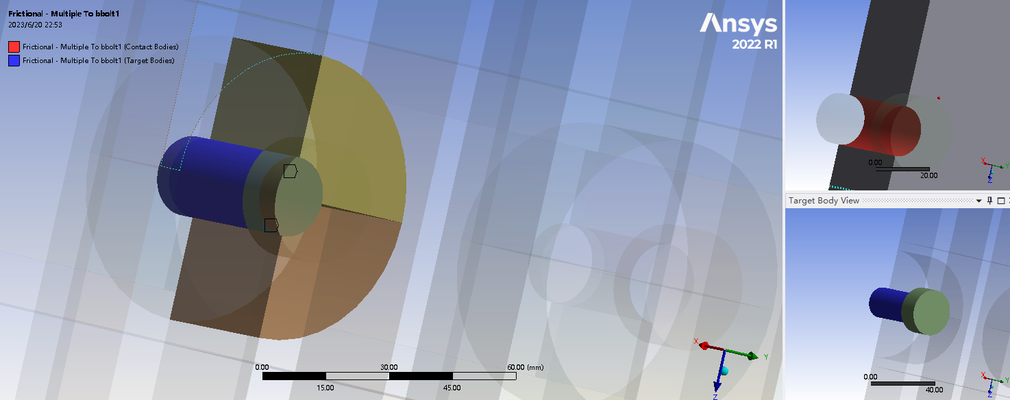
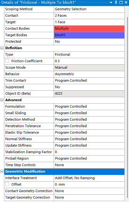
I guess both led to divergence of solutions. In Fig. 3, I also attached a screenshots of the initial info of the frictional contact i defined for the bolt and CZM bonded contact.
Hope someone can give some help for me. Thank you very much!
Regards,
-
June 20, 2023 at 7:14 pm
John Doyle
Ansys EmployeeYou could wrap contact scoping around the edges and switch detection method to 'combined' to use both gauss and nodal detection together. Also, try dropping midside nodes.
-
June 21, 2023 at 6:01 am
wancheng gao
SubscriberHello John, it is really helpful to receive your reply.
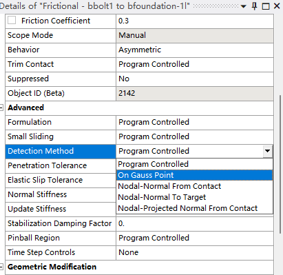
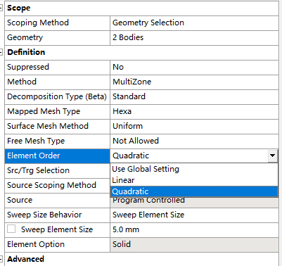
Can you explain a little bit about “wrap contact scoping around the edges”?I don’t really get this. The bolt gets contact with the bolt hole. My understanding is the frictional contact should be created between the bolt surface and bolt hole inner surface. How can I get the contact scoped to the edges? Please refer to the following figures which show how I created the frictional contacts. The bolt shank surface have two seperate frictional contacts with the left part of the surrounding material as well as the right part of the surrounding material, respectively. THe reason why the material were separated into left and right parts is I have to create the Cohesive zone model in between the interface. The settings are also shown.
I can’t find the “combined” detection method in the settings. Will it only appear after the contact scoping is changed to edges?
The last question, to drop the midside nodes, do you imply the element order? I will change it to linear element.
Appreciate your reply and professional advice!
Kind regards.
-
June 22, 2023 at 7:04 am
wancheng gao
SubscriberHello John, I have been thinking about what you advised that Wraping the contact around the edges. Do you indicate that I should create one sinlge frictional contact for both parts at the bolt hole. i.e. around the edges. Is the "combined" detection method the new function in ansys 2023? I am using 2022 R1 right now.
Really appreciate your could give some guidance at your convenience.
Kind regards,
-
-
- The topic ‘Highly distorted elements near bolt holes’ is closed to new replies.


-
4613
-
1530
-
1386
-
1209
-
1021

© 2025 Copyright ANSYS, Inc. All rights reserved.

