-
-
December 3, 2018 at 7:05 am
shubham14
SubscriberI am trying to simulate a 2D contact problem with very high displacement BC's and getting an error that element has highly distorted. Because of that solution is not converging. I have tried with increasing the number of load step and sub steps but it is not helpful. Some elements are flipping because of very high displacement, so how can i solve this highly distorted element error.Â
Any advice or help would be appreciable.Â
Â
-
December 3, 2018 at 3:14 pm
Sandeep Medikonda
Ansys EmployeeHi Shubham,
If the application detects more than one instance of the error during the solver's iterative process, then a message for the last instance is reported. The application obtains errors from file.err in the solver files directory.
Use the Identify Element Violations property on the Solution Information object to generate Named Selections for the offending element(s).
Also, request and look at the Newton-Raphson residuals. This should give you more insight. See here.
Lastly, focus on the material properties, what are you using here?
Regards,
Sandeep
Guidelines to the Student Community -
December 3, 2018 at 3:25 pm
jj77
SubscriberIf it is not a secret which I doubt it is since this looks like a a standard test, and this is a student forum, feel free to upload the files so someone kind enough can have a look.
-
December 4, 2018 at 3:22 am
peteroznewman
SubscriberIt looks like you need a much finer mesh on the pin doing the indenting and the object being indented.
-
December 4, 2018 at 5:08 am
shubham14
SubscriberHi Peter,
Thanks for your suggestion, but i have tried with local refined mesh at the contact area and that was also showing distorted element error. Only in case when i am using very coarse mesh throughout the geometry then only i am getting a converge solution. But that mesh size is very coarse, that why it is not distorted. so how can i get converge solution with fine mesh.
Thanks,
ShubhamÂ
-
December 4, 2018 at 7:37 am
shubham14
SubscriberHi Sandeep,
Thanks for pointing some important things.
Here in this simulation i created a material which has E= 100 KPa and poisson's ratio of 0.49.Â
i have tried the things that is mentioned in the link like reduce normal stiffness upto 0.2Â and changed Detection method for contact elements from program control to Nodal-Normal to Target. Bur still solution is not converging because of elements are still distorted.
Regards,
ShubhamÂ
-
December 4, 2018 at 5:34 pm
peteroznewman
SubscriberIs this 2D model Axisymmetric or Plane Strain?
I assume you have already turned on Large Deflection in the Analysis settings?
I can't see the tip of your poker. It cannot have a square corner (except for on the symmetry plane or axis, which is not really a corner), you must put a radius on the corner of the poker. There must be at least four elements around that radius on both the poker and the ball. That is what I am talking about small elements. If you have a square corner on the poker, that is the reason why you are getting distorted elements.
In addition to small elements, you need to enforce many substeps using Minimum Substeps.
The poisson's ratio is nearly incompressible. There are other things you need.
You might also need Reduced Integration Elements. This link is to an older version of software, 19.2 put this in a different place.
You might also need a Key Ops on the element to help with the large strain.
You might also need to change to Hyperelastic Material Properties.
Regards,
Peter -
December 5, 2018 at 9:59 am
shubham14
SubscriberHi Peter,
yeah, it is 2D model Axisymmetric and i have putted 1 micron thickness (thickness is mandatory even in 2D model) with 120 micron diameter of semi circle and i have already turned on Large Displacement in the Analysis setting.
I have putted 45 steps with max 500 subteps in each steps for 45 micron displacement. And i using Linear isotropic material with 100 KPa Young's modulus and 0.49 Poisson's ratio. And where in will get Reduced integration Elements.
Â
Thanks and Regards,
Shubham
-
December 5, 2018 at 12:46 pm
peteroznewman
SubscriberHi Shubham,
"thickness is mandatory even in 2D model"Â This is not true, you have made a mistake somewhere.Â
Create a new Static Structural system in Workbench, RMB on the Geometry cell and select Properties. In the Properties window on the right side of Workbench, there is Analysis Type that defaults to 3D. Change that to 2D. NOTE: If you already built a model, you cannot go back and change 3D to 2D after the geometry was attached to the Model. You must start over.
Now start the Geometry Editor. Create the surfaces in the XY plane with the axis of rotation along the Y axis. These are surfaces, not 3D solids.
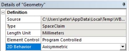
Double click on Model to start Mechanical. Click on Geometry. In the Details window, you can set the 2D Behavior to Axisymmetric. No thickness is required.Â
Please reply with confirmation that you have done all these steps.
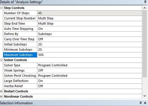
On the substeps, you didn't say you set the minimum substeps. I don't care about the max substeps. And 45 substeps may not be enough, you might need 100 or more.
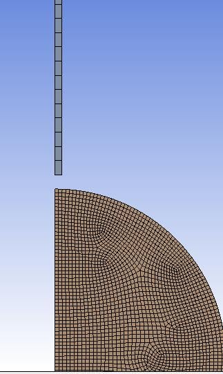
Please reply with a zoomed in view of the elements around the tip of the rod.
Kind regards,
Peter -
December 6, 2018 at 6:03 am
-
- The topic ‘Highly distorted element error’ is closed to new replies.
-
4607
-
1510
-
1386
-
1209
-
1021
© 2025 Copyright ANSYS, Inc. All rights reserved.


