
TAGGED: composite-material, static-structural
-
-
June 6, 2021 at 4:17 pm
rahmanmahfuz11
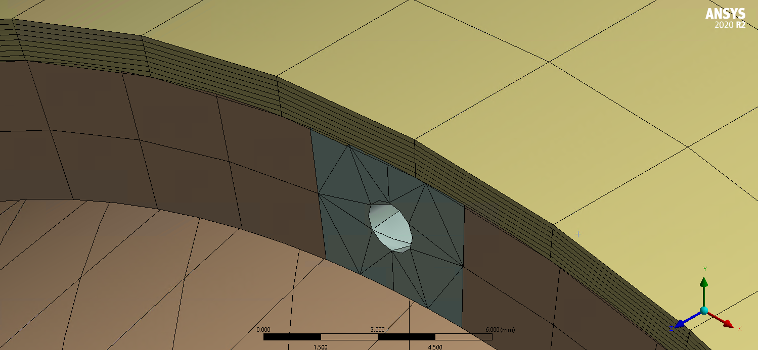
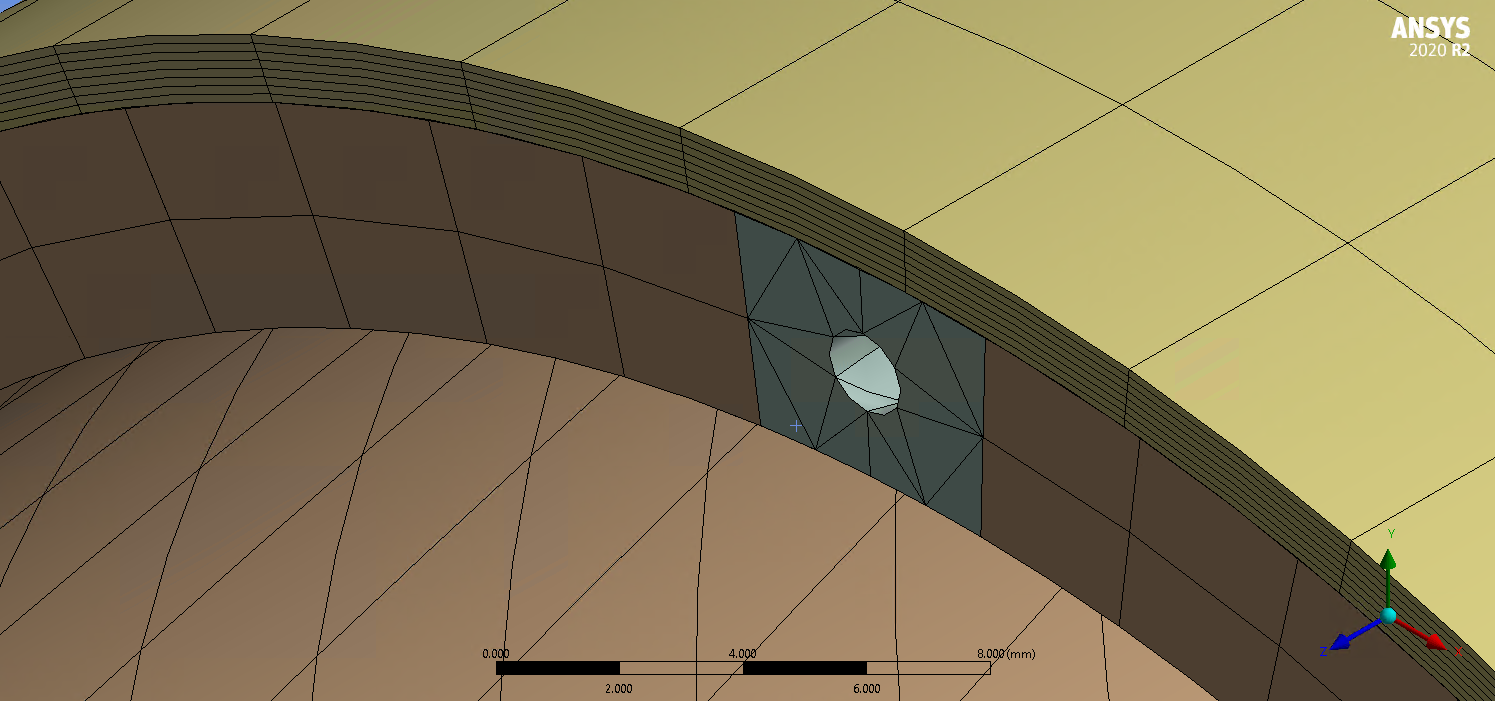
SubscriberHello all, I am modeling a carbon fiber composite tube with a 4mm HDPE layer with a helical hole of 1.5mm diameter inside. The following figure shows the HDPE layer with the hole.
June 6, 2021 at 7:52 pmpeteroznewman
SubscriberI think the high stress is an artifact of the non-congruent mesh. Look at the large overlap of the one mesh with the other.
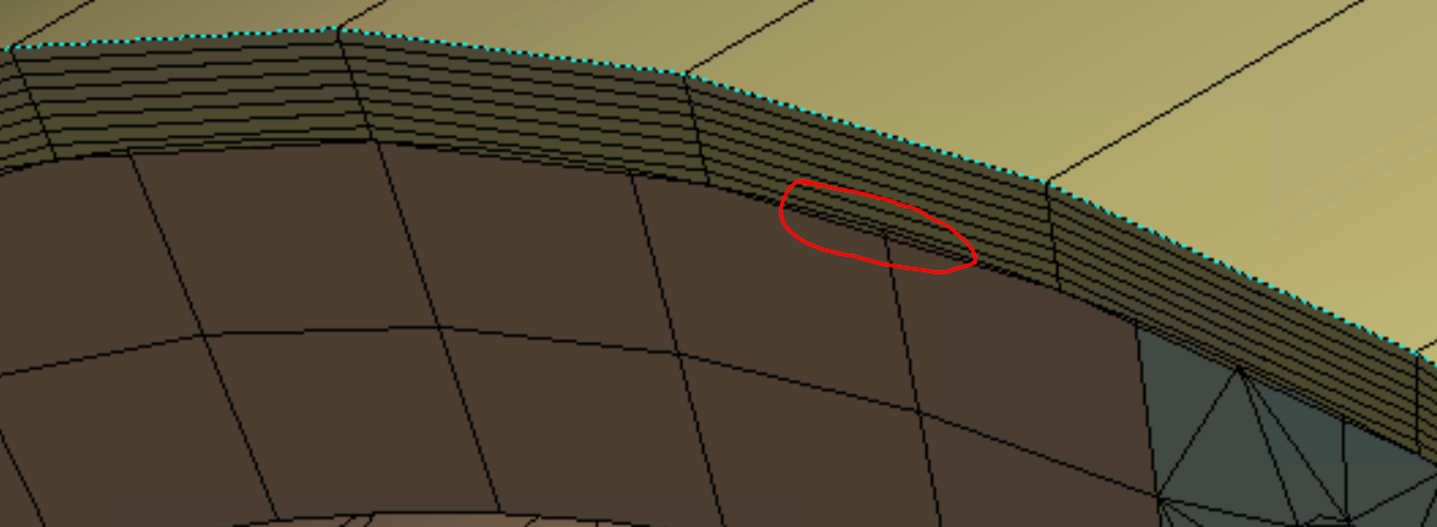 Discard the bonded contact and use shared topology to obtain a congruent mesh so that there are no nodes that overlap into the adjacent material and I expect the stress will not be so large.
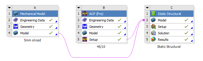
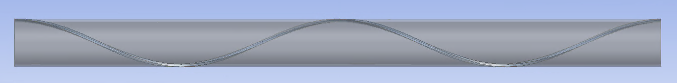
June 7, 2021 at 7:40 amSubscriberThank you for the reply. The bonded contact is in between the composite layers & thermoplastic solid. The composite layers are coming from ACP and the solid thermoplastic layer is coming from Mechanical Model like the picture attached below. Can I use a shared topology between two different models? If not, then how else can I overcome this issue? thank you!
June 7, 2021 at 5:30 pmSubscriberI don't know if you can use shared topology with ACP shell and normal solid model mesh. I suppose if there was a common geometry model that shared topology, and the face was meshed in ACP and the solid was meshed in normal model it might work.
If not, you can always slice the common geometry and imprint features onto each geometry set so that mesh controls will allow a congruent mesh to be made in both models, and a node merge operation issued instead of using bonded contact.
If you can't manage to eliminate bonded contact, does ACP permit quadratic elements? Using quadratic elements in both systems would reduce the amount of mesh penetration. If you must use linear elements, making the elements smaller will reduce the penetration.
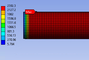
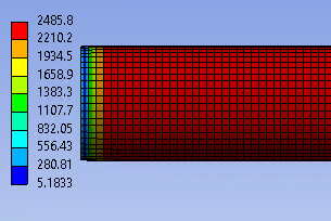
June 9, 2021 at 7:04 pmSubscriberI have used the quadratic elements. They did reduce the penetration of mesh, thank you. But with quadratic elements, I am getting more stress than linear elements. The results in the original post are faulty for another reason. I made a mistake in the surface selection for loading. These are the original stress results with linear elements:
And these are with quad.
Viewing 4 reply threads- The topic ‘High stress difference in between two adjacent layers in a composite tube’ is closed to new replies.
Ansys Innovation Space Trending discussions
 Top Contributors
-
peteroznewman
 3145
3145 -
javat33489
 1007
1007 -
scabo
 935
935 -
Shyam Prasad V Atri
 858
858 -
adib.aktab999
792
Top Rated Tags
© 2025 Copyright ANSYS, Inc. All rights reserved.
Ansys does not support the usage of unauthorized Ansys software. Please visit www.ansys.com to obtain an official distribution.
-


The Ansys Learning Forum is a public forum. You are prohibited from providing (i) information that is confidential to You, your employer, or any third party, (ii) Personal Data or individually identifiable health information, (iii) any information that is U.S. Government Classified, Controlled Unclassified Information, International Traffic in Arms Regulators (ITAR) or Export Administration Regulators (EAR) controlled or otherwise have been determined by the United States Government or by a foreign government to require protection against unauthorized disclosure for reasons of national security, or (iv) topics or information restricted by the People's Republic of China data protection and privacy laws.


