TAGGED: antenna, antenna-design, hfss, NFC, s11, simulation
-
-
March 3, 2023 at 10:51 am
simay açıkel
Subscriber
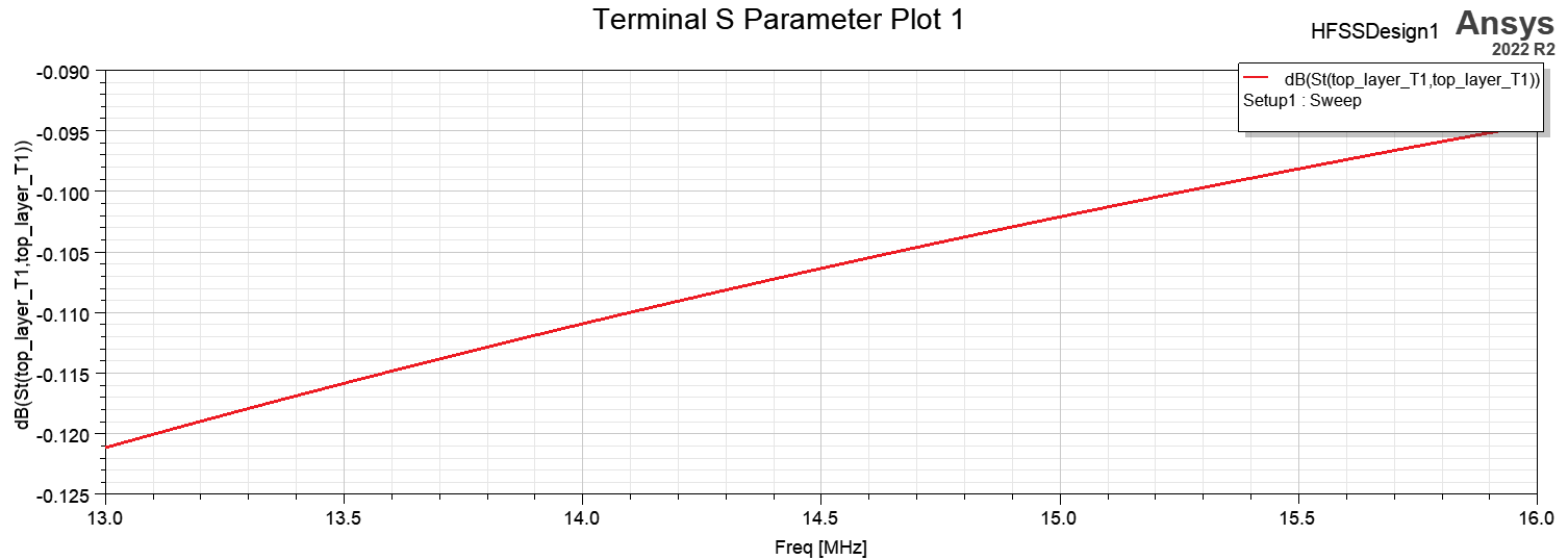
I am trying NFC antenna simulation getting S11 parameters(at 13.56Mhz) but I am new member user of HFSS ANSYS. I coundt reach correct result. This is my S11 graphic;
I followed these steps,
1)I imported ODB from Altium to HFSS
2)I enter setup(analysis) as 13.56Mhz I deleted ic.
3)Exported HFSS Model.(second photo)
Â
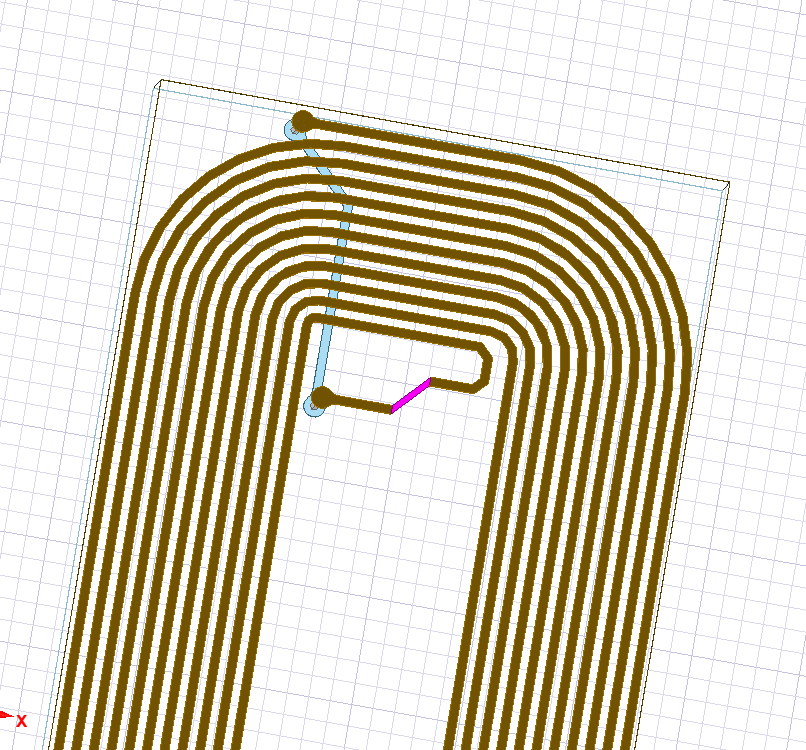
4) I created sheet than assiged it as lumped port.
Where do i make wrong? Are all steps okay? Could you help me?
By the way after that I have to put capacitor between two trace of antenna to match tunning how can add 50pF capacitor between trace of antenna in the easiest way.
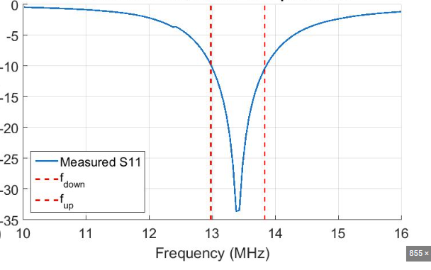
the result to achieve is as follows;
Â
Thank you
-
March 27, 2023 at 12:47 pm
Praneeth
Forum ModeratorHi Simay,Â
Thank you for reaching out and your patience is much appreciated.
It looks like your setup is not correctly set for the antenna simulation. As you are a new user, it is suggested to go through the getting started guides (GSG) which can help you with a correct simulation setup. Go through - probe fed patch antenna GSG to learn the detailed steps available in the Help menu. Alternatively, you can access the online version of this GSG here - Ansys Electronics 2023 R1 - Set Up the Project.Â
Additionally, you can also go through antenna examples to get hands-on experience with antenna simulation in Ansys HFSS.
Best regards,
Praneeth.
-
- The topic ‘HFSS NFC ANTENNA SIMULATION’ is closed to new replies.
-
3402
-
1052
-
1051
-
896
-
877
© 2025 Copyright ANSYS, Inc. All rights reserved.