Hello all,
I dont think I fully understand what HFSS does when you deembed a waveport into a simulation. In my understanding, deembedding is simply moving the refence plane of the simulation further into the model by some distance, effectively ignoring any interactions or reflections prior to the deembedding distance. Perhaps someone can help me to understand where I am mistaken.
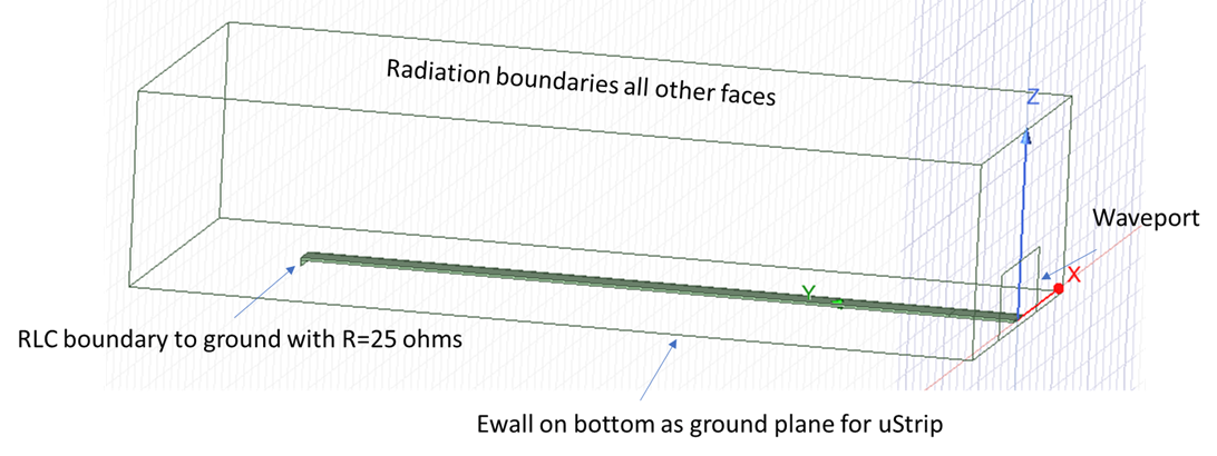
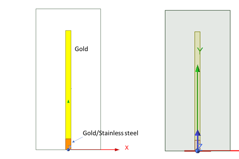
To test my understanding and give something to discuss I made a very basic simulation. On the top left is a picture of the simulation. A single microstrip line within a vacuum box, that is terminated with a 25Ohm RLC boundary. The waveport is set not to re-normalize the data to ignore any mismatches at the port. On the top right is a top view of the simulation. The ustrip line is separated into two pieces of metal. For one simulation, the ustrip line is all gold, for a second simulation the input tap of metal is changed to stainless steel (something with low conductivity). In both simulations I set the port to deembed past the input tab by twice the tab's lenght. To make sure I am comparing apples to apples, both simulations share the exact same mesh and have the same number of meshing elements. The convergence looked ok, and i would expect HFSS to do well on such a simple strucutre. My inital notion of deembeeding would lead me to think the results should be indetical since I am deembdding past the discontinty in the metal line.
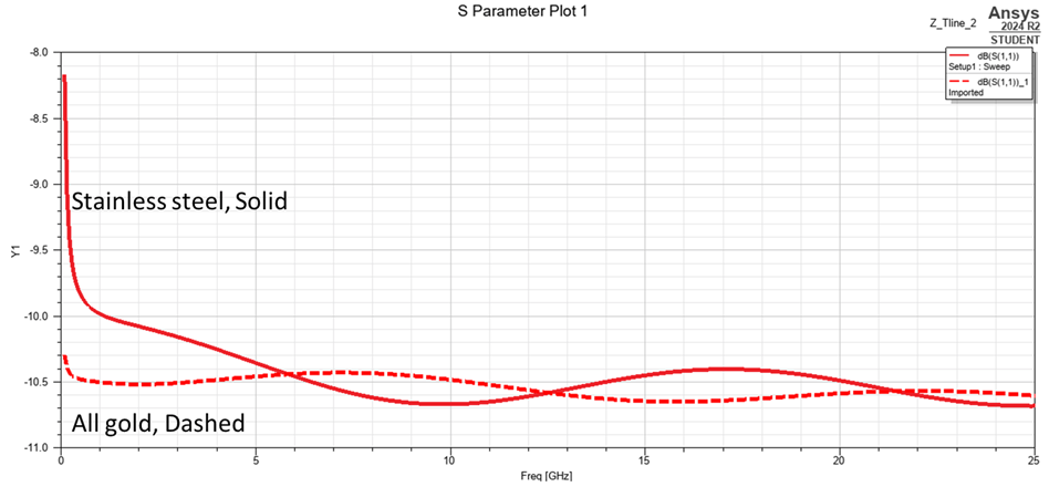
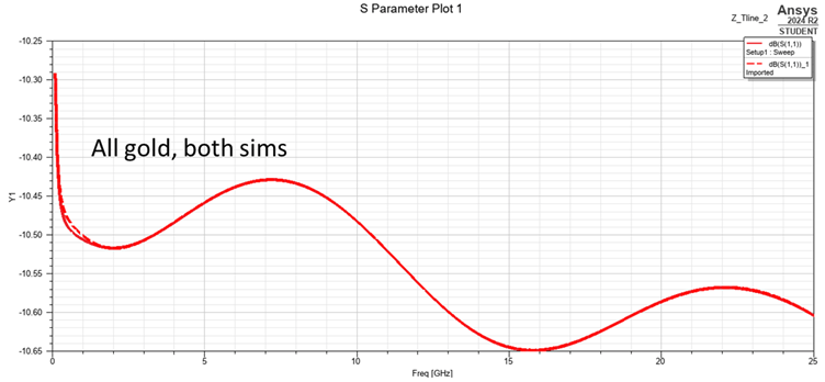
However, as the plot on the left shows, the results are different despite deembedding. Just as a sanity check, the the plot on the right compares the sims with all the ustip lines being gold and the results being almost identical (although i still wouldn't have expected the little blip either). This is a confusing results given my previous, incorrect view of what deembedding is doing. Does anyone have any thoughts?
Happy to provide more context on the problem if people need, Thanks!


