-
-
May 21, 2021 at 10:21 am
morganj32
SubscriberI am trying to do fatigue analysis of a brake disc for a university project but I am having difficulty getting a realistic, working model. If anyone can give me any help or point me towards some resources I can use I would be very grateful.
The first thing I tried was to fix the inside of the bolt holes, apply the clamping forces to the disc via the pads and apply a rotational velocity to the disc body which goes from the car's top speed to stationary over around 1.6s, however I believe this will not simulate what is really happening. With this set up the disc will be rotating while the bolt holes do not but in reality the bolt holes rotate with the disc and only the pads are stationary. This set up is shown in the picture below.
May 21, 2021 at 1:00 pmAshish Khemka
Forum Moderator
Rotational velocity accounts for the structural effects of a part spinning at a constant rate and you will not be able to see the motion. Instead using a joint load is a better approach. You are seeing an unconverged result. What is the deformation say at 1.5s. Is the disc rotating as expected?
Regards Ashish Khemka
May 21, 2021 at 1:03 pm1shan
Ansys EmployeeYou can't provide a fix support and rotation to the same body. You need to delete the fixed support and just add a body ground revolute joint scoped to the bolt holes. Next you need to specify a translation joint to the pad bolt surfaces. Insert 2 joint loads one for each joint defined. In the first load scoped to the revolute joint add rotation/angular velocity and for the second add a small displacement (equal to the pad actuation) to press the bad against the disk. I hope you defined a frictional contact between the 2. There is a very similar tutorial on ansys innovation courses check it out /courses/index.php/courses/mechanical-strain/lessons/lesson-7-homework-quizzes-simulation-examples-mechanical-strain-in-deformation-analysis/.
Regards Ishan.
May 21, 2021 at 2:53 pmSubscribergood point about the rotational velocity and not seeing the motion, that seems obvious now you've pointed it out! Unfortunately the result is still not as expected earlier in time unless the rotational velocity (via the joint load) is very small. Thank you for your help so far.
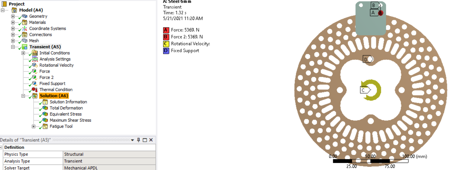
thank you for your help! Since I posted my first message I did something very similar to what you suggested but used a force with the translational joints instead of a displacement to represent the clamping force applied by the braking system. The joint is applied to the back faces of the pads and they are set to rigid and I have a frictional contact between each pad and the disc.
As before, with low velocities (about 1 rad/s) it is fine but with the ones I actually need to use (around 130 rad/s) I get an unconverged solution and crazy deformation like shown below, do you have any idea why? The screenshot shows the constraints too but I am happy to provide more detail. With either velocity I get a warning that there does not appear to be enough constraints to prevent rigid body motion but I am not sure what is the most suitable way to add those right now.
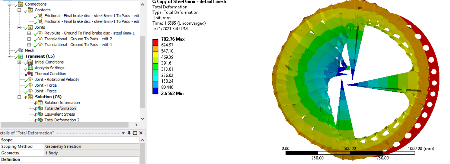
May 21, 2021 at 3:07 pmSubscriberThis was all done with large deflection turned on (with it off I get warnings that suggest I should use it). I have just done the same simulation without it and with a frictionless support applied to the large faces of the disc and the outer face and instead of the disc twisting and deforming it basically just expands outwards, from its original approx. 200mm diameter to around 10m in diameter, there's no rotation like there is on the lower velocity simulations either. I'm not sure what to make of this but thought I would add it as a note in case it helps anyone to help me.
I have also just ran with large deflection off but without the frictionless support and once again the blade twists and deforms.
May 21, 2021 at 4:06 pmForum Moderator
Please see if the following link helps:
https://www.youtube.com/watch?v=Ko-RIQEX0LQ
Regards Ashish Khemka
May 21, 2021 at 4:42 pmSubscriberI have seen that before, my set up seems to be the same other than I have used a force instead of displacement for the translational joints. That video is at a very low rotational speed though which is not a problem for me.
I have found these forum discussions that describe a similar problem to mine so I am investigating different step sizes.
Viewing 6 reply threads- The topic ‘Help With Transient Structural Brake Disc Analysis’ is closed to new replies.
Innovation Space Trending discussions
- LPBF Simulation of dissimilar materials in ANSYS mechanical (Thermal Transient)
- Real Life Example of a non-symmetric eigenvalue problem
- How can the results of Pressures and Motions for all elements be obtained?
- BackGround Color
- Contact stiffness too big
- Element Birth and Death
- Python-Script to Export all Children of a Solution Tree
- Which equations and in what form are valid for defining excitations?
Top Contributors
-
peteroznewman
 4597
4597 -
scabo
 1495
1495 -
Dennis Chen
 1386
1386 -
javat33489
 1209
1209 -
Shyam Prasad V Atri
1021
Top Rated Tags
© 2025 Copyright ANSYS, Inc. All rights reserved.
Ansys does not support the usage of unauthorized Ansys software. Please visit www.ansys.com to obtain an official distribution.
-
General Mechanical
Topics related to Mechanical Enterprise, Motion, Additive Print and more.
Help With Transient Structural Brake Disc Analysis


Ansys Assistant

Welcome to Ansys Assistant!
An AI-based virtual assistant for active Ansys Academic Customers. Please login using your university issued email address.

Hey there, you are quite inquisitive! You have hit your hourly question limit. Please retry after '10' minutes. For questions, please reach out to ansyslearn@ansys.com.
RETRY