

TAGGED: -quasi-static, load-step, mechanical
-
-
November 20, 2024 at 8:52 am
mhannan
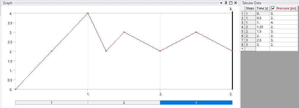
SubscriberHey, I am doing quasistatic analysis in static structural module of ansys. My whole load curve is for 3 second and it’s not linear or constant load for 3 second. The loads changes within a very short time like 1 have almost 30point of load in between 0 to 1 second. There are almost 137 points of load in the whole 3 sec curve and loads for all the 137 points are different.
How can I get result for the individual 137 points ??
This loads are my input pressure and how can I get output for the all individual point(input points of pressure vs time are generated from the graph by webplotvisualizer) in ansys static structural.
-
November 20, 2024 at 12:48 pm
peteroznewman
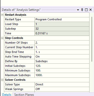
SubscriberIn Static Structural, under Analysis Settings, Step Controls, you can set the Number of Steps to 3 and set the Step End Time for each step to 1, 2 and 3 s.
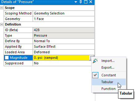
In the Pressure load, there is a pull down menu that allows you to select Tabular data input.
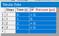
In the Tabular data window, click once in the blank cell to the left of Steps to select the whole table.
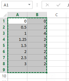
In Excel, copy the 2 columns and 137 rows of numbers plus one blank row at the bottom. In Mechanical, right click on that same blank cell in Tabular data and select Paste. My example shows 8 rows of data and I have selected 9 rows to copy.
You can do the same thing with just one Step. Just set the End time to 3 and copy paste the data in the same way and you will get the same load history.
Finally, you want to force the solver to take small enough time steps to not skip over any part of the load history. Under Analysis Settings, change Auto Time Stepping to On then Define By Time. Set the Initial and Maximum Time Step to a value smaller than the smallest time increment in your table. Set the Minimum Time Step to a value one tenth of that smallest time increment.
If you used one load step of 3 s you are done. If you used 3 load steps, you have to repeat the previous paragraph two more times for each load step.
-
November 25, 2024 at 9:01 amSubscriber
hey, I tried your process and I faced errors:
error1: The unconverged solution (identified as Substep 999999) is output for analysis debug purposes. Results at this time should not be used for any other purpose.
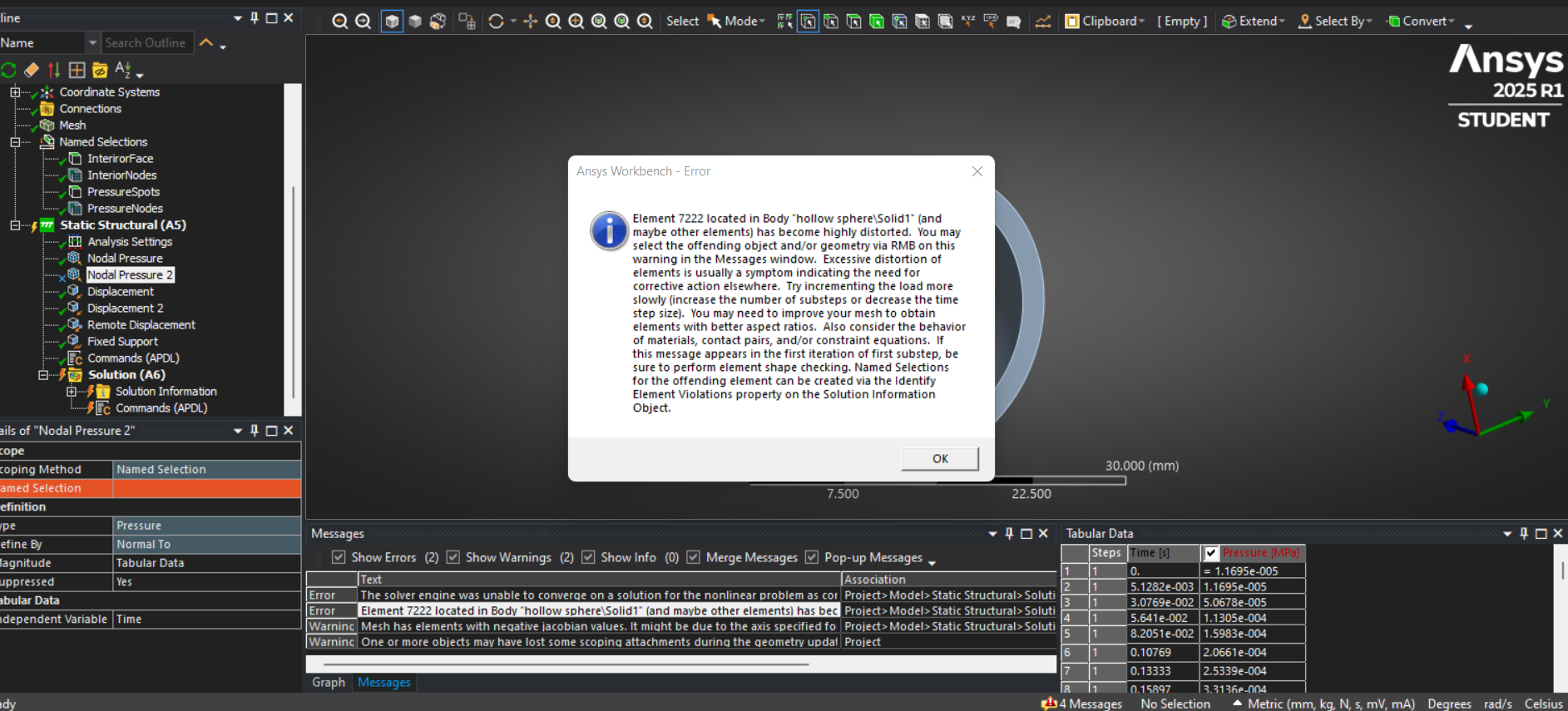
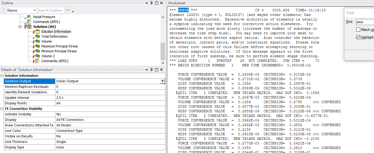
error2: Element 10365 located in Body "for fsi - Copy|Sclera" (and maybe other elements) has become highly distorted. You may select the offending object and/or geometry via RMB on this warning in the Messages window. Excessive distortion of elements is usually a symptom indicating the need for corrective action elsewhere. Try incrementing the load more slowly (increase the number of substeps or decrease the time step size). You may need to improve your mesh to obtain elements with better aspect ratios. Also consider the behavior of materials, contact pairs, and/or constraint equations. If this message appears in the first iteration of first substep, be sure to perform element shape checking. Named Selections for the offending element can be created via the Identify Element Violations property on the Solution Information Object.
warning 1: The unconverged solution (identified as Substep 999999) is output for analysis debug purposes. Results at this time should not be used for any other purpose.
warning 2: Solver pivot warnings or errors have been encountered during the solution. This is usually a result of an ill conditioned matrix possibly due to unreasonable material properties, an under constrained model, or contact related issues. Check results carefully.
https://drive.google.com/file/d/1EHkE4lLSBiPs3Mqmd5lNLObQtBCc4mmJ/view?usp=sharing
-
November 28, 2024 at 9:34 pmSubscriber
I can't open your model because it contains modules that are not included in the free Student license.
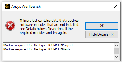
Try deleting the mesh and archive the project with no mesh, then upload that archive to see if that helps me to open it.
-
-
November 28, 2024 at 9:27 pmSubscriber
The process I provided was to import 127 rows of time history into the pressure load, you must follow a different process to obtain convergence.
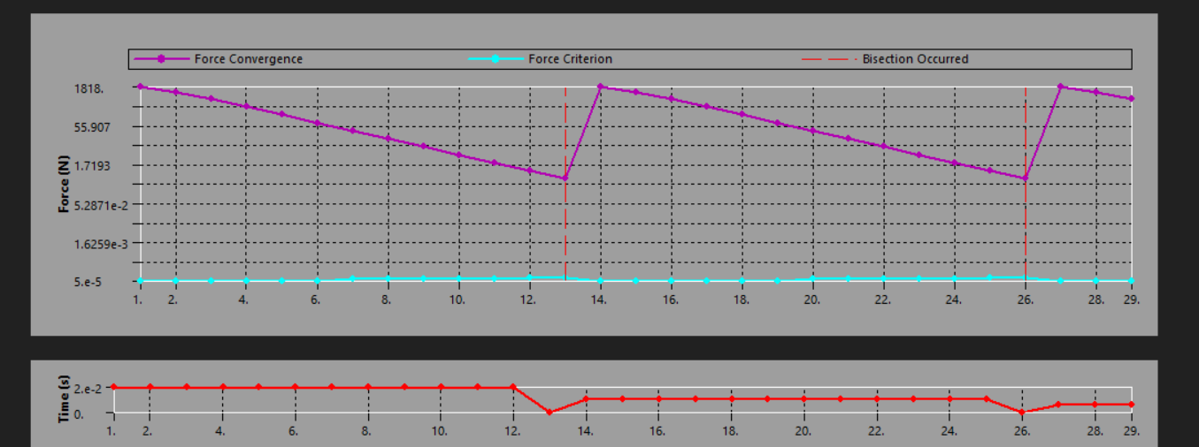
The highly distorted error message contains some good advice which you should follow. Try incrementing the load more slowly (increase the number of substeps or decrease the time step size). You know where to find that. It is helpful to first look at the Force Convergence plot under the Solution Information folder. The graph shows you what time the solver ran into problems converging. The graph also shows you how many times the automatic time stepping algorithm used bisection to reduce the time increment. You can also change the plot to show the size of the time increment vs time.
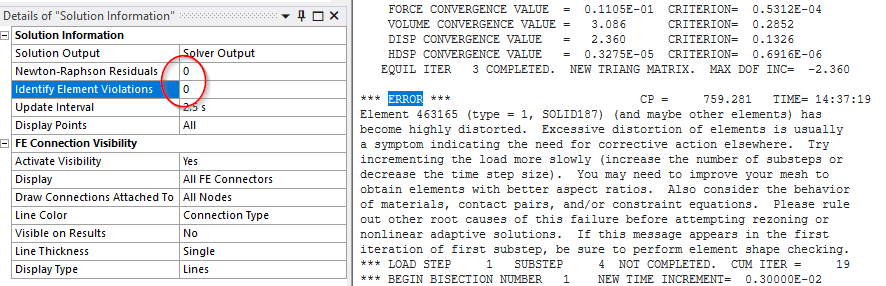
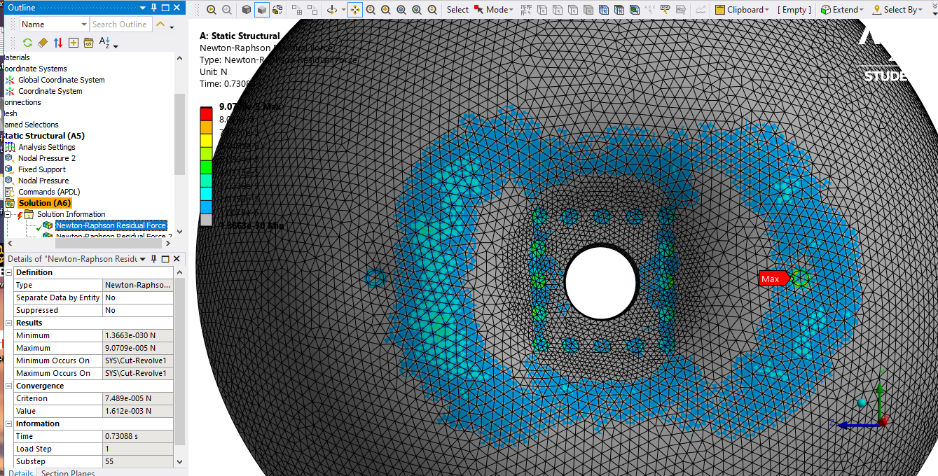
Another piece of advice in the error message mentions that you may need to improve the mesh. However, you need to know where on the mesh the solver is having difficulty converging. To see that, edit the Analysis Settings. Click on the Solution Information folder and on the line that says Newton-Raphson enter a number, say 3. This will make 3 contour plots under this folder that show you where on the mesh the force imbalance was largest for the last three iterations. If there are large elements there, you may need smaller elements or if the elements are of low quality, you may need to improve the shape.
-
December 1, 2024 at 7:58 amSubscriber
Rather than time step, I use step number and now the simulation converges, can you look into this???
I am also facing problems in implementing subroutine, can you tell me the process?https://drive.google.com/file/d/1g1vRm8BfO_--YiE75Kg3b2pGuTZTStO2/view?usp=drive_link
-
December 2, 2024 at 12:49 amSubscriber
I was able to open the model and look at the solid bodies where I noticed that there is a body called Lens and another identical body called NONE. They are both meshed. Is that intentional or a mistake?
-
December 29, 2024 at 11:03 amSubscriber
As they are different object so I mesh the both body, can I get your mail where you can respond faster?
-
December 29, 2024 at 2:54 pmSubscriber
I check here more frequently than I check my email, so it's faster to reply here.
In the model, you have two bodies that take up the same space, which is not a normal situation in reality. That looks like a mistake in the model.
-
January 3, 2025 at 5:56 pmSubscriber
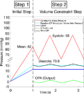
if you see the part choroid, this part should change it’s volume overtime with the changing of pressure which are exerted by the 18 nodes by using nodal pressure. And the part called inside is actually vitrious body which is fully incompressible(So I modeled as water) when the choroid changes it’s volume, it’ll affect vitrious body and as it can’t change it’s volume it’ll create an opposite pressure to resist it’s volume deformity. I need to extract the pressure. Below part is the modeling of the opposite pressure which is named OPA in FEBio:
”To estimate the OPA in all models, a ‘‘volume constraint’’
was imposed on the inner limiting membrane and the
augmented Lagrangian was turned on. The tolerance and
penalty factor were set as 0.00001 and 0.001, respectively.
Those values were chosen because they maintained the
volume of the vitreous within 0.000001% during the cardiac
cycle. All pressure estimates (to maintain the volume of the
vitreous body constant) were extracted from the FEBio output
log file (.log) under the section ‘‘Volume Constraint’’ at each
converged step.”
here is the ipdated model
https://drive.google.com/drive/folders/19FQFr4y9Cpfm5TyeTlqGjdfvhFeVS1jQ?usp=sharing
Also please check me the APDL, and can yopu tell me how can insert effective permeability.
I need your help badly, please reply me soon.
thanks in advance. -
January 4, 2025 at 4:15 pmSubscriber
You have assigned the material WATER3, which was defined using Isotropic Elasticity, to the Inside body. This is a big mistake because WATER3 has a huge Shear Modulus, while real water has zero Shear Modulus. This will cause a large error in your results. Delete the Inside body and instead use the faces of the solid elements that define the inside cavity surface to create HSFLD242 elements.
HSFLD242 is used to model fluids that are fully enclosed by solids (containing vessels). The hydrostatic fluid element is well suited for calculating fluid volume and pressure for coupled problems involving fluid-solid interaction. The pressure in the fluid volume is assumed to be uniform (no pressure gradients). Hydrostatic fluid elements are overlaid on the faces of 3D solid or shell elements enclosing the fluid volume.
-
January 4, 2025 at 4:25 pmSubscriber
You ask about effective permeability, which is related to fluid flow through porous materials. You must use a different solver for that such as Fluent. Here is the Fluent tutorial on modelling flow though porus media.
Another environment to build porous models is Discovery. Here is the Discovery help page.
Here is the Discovery Porus media coefficient calculator.
There is a theory course on Flow through Porus Media.
-
January 5, 2025 at 5:45 amSubscriber
Actually I need to add volume constrains and make the body called inside fully incompressible so that it can’t change it’s volume overtime. As water is incompressible so I think it will work. Can you tell me how can I add volume constrains and get the pressure as a result. Do you think HSFLD242 will work in my case??
If this work then how will I incorporate it in my model?
I have to define choroid’s material property as Biphasic, where the solid volume fraction is 0.55.
The solid portion is defined as Neo Hookian model with model parameter :
Elastic modulus = 0.06 MPa
Poisson’s ratio = 0
Permeability: 45037 mm2/MPa.s
How can I input this into ansys?
Also I need to measure the volume change of choroid but after applying nodal pressure(nodal pressure for modeling cilliary artery), there is no change of volume which I measure from “volume” result window. Below is the example: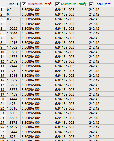
-
January 5, 2025 at 3:01 pmSubscriber
The HSFLD242 elements include a pressure node at the center to report the pressure in fluid and can be defined as fully incompressible using KEYOPT(6) which defines the hydrostatic fluid element compressibility:
Use KEYOPT(6) = 0 (default) to model the hydrostatic fluid element as compressible. You need to define a fluid material property (use the TB command with Lab= FLUID) to relate changes in fluid pressure to fluid volume.Use KEYOPT(6) = 1 or 2 to model the hydrostatic fluid element as incompressible. The fluid volume is kept constant, even as the solid enclosing the fluid undergoes large deformations. The fluid volume, however, can change when fluid mass is added to or taken out of the containing vessel; this is achieved by applying a fluid mass flow rate or by prescribing a non-zero hydrostatic pressure degree-of-freedom constraint at the pressure node. The fluid volume can also change when a temperature load is applied at the pressure node for a fluid with a non-zero coefficient of thermal expansion. When KEYOPT(6) = 1, the change in volume is accommodated by a change in fluid mass (mass flows into or out of the cavity). When KEYOPT(6) = 2, the change in volume is accommodated by a change in fluid density such that fluid mass is held constant. Read Chapter 15 for how to model hydrostatic fluid models.
Note that HSFLD242 elements must have the shape of a pyramid, with the pressure node at the apex in the center of the cavity. That means the solid elements that define the enclosed volume must be either pyramid or hex elements. Your current mesh uses tetrahedral elements, which is incompatible with HSFLD242 elements. A significant effort would be required to achieve hex element meshing throughout your model. The benefits of using HSFLD242 elements is that it has a direct pressure output that is constant over the entire fluid volume and there is a fluid volume output.
If you mesh the solid Inside body with tetrahedral elements, assign a water property defined with orthotropic elastic material properties so you can set the Shear Modulus to practically zero. This discussion that has my definition of water that has a practically zero shear modulus. The benefit is the meshing is easy. You can create a stress ouput for hydrostatic stress, but it may vary throughout the volume.
-
January 5, 2025 at 3:54 pmSubscriber
The last model you shared uses a Static Structural analysis, but since you want to include Coupled Pore-Fluid Diffusion and Structural Model of Porous Media, you might want to select the Coupled Field Static analysis from the toolbox. Read Chapter 2.12 to learn how to perform this type of analysis.
The material models supported in the coupled structural-pore-fluid-diffusion analysis include elasticity (isotropic, orthotropic and anisotropic), porous elasticity, Mohr Coulomb plasticity, Cam-clay plasticity, jointed rock plasticity, extended Drucker-Prager and Drucker-Prager-based concrete plasticity.
Porous elasticity material can be defined with an Initial void ratio, which would be 0.45 to give you a solid volume fraction of 0.55
Note that Hyperelastic material models are not on the list of material that support pore-fluid diffusion. I don’t know where you want the pore-fluid diffusion to act, but you have used Hyperelastic materials such as Yeoh for Piamater and Duramater, Mooney-Revlin for Sclera and Neo-Hookean for Choroid. However, I find in Engineering Data, it does not complain if I add Porous Elasticity to a Neo-Hookean material, but maybe they just haven’t put all the error checking in that is required. For many illegal combinations, Engineering Data will use a strike-though font so highlight illegal combinations in material properties.
Note that you must mesh the bodies that will have permeability with the correct element type that supports coupled pore pressure analysis such as CPT217.
There are two Verification Test models of coupled pore-pressure deformations. One is a 2D model VM260. VM264 is a 3D model using CPT217. I see they use Analysis Type of Static (ANTYPE,0) so maybe you don’t have to use ANTYPE,SOIL which was mentioned in 2.12 above.
In the last model you sent, I see the volume changes in Step 1, but not in Steps 2 and 3. Maybe when you get a model that includes pore-fluid diffusion, you will see a volume change.

-
-
January 10, 2025 at 5:34 pmSubscriber
I think the pressure which I was applying through nodes aren't working, I have experimented on a simplified model. How to handle this issue?
-
January 10, 2025 at 11:42 pmSubscriber
You have a very complex model that uses many types of material properties and is a coupled physics type of model. I suggest you build competence in each component of this complex model by analyzing many much simpler test models and you indicate above that you have already started to look at a simplified model. Please describe in detail that simplifed model, what result you obtained and why you think it is wrong.
The ideal simple test model is one which has an analytical solution so you can show that your model result matches the analytical model. The ideal simple test model may have geometry very different than your eyeball anatomy. The verification model VM264 is a simple cylinder.
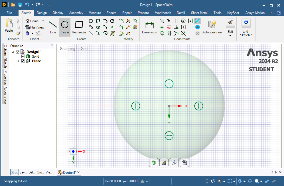
Another simple test model is a volume of water inside a non-porus elastic (or hyperelastic) enclosure with a constant wall thickness. Use a simple geometry such as a sphere and show that you can apply pressure to one face and have the other faces expand out while the volume of water remains constant. I would use symmetry to make the boundary conditions simple. Use SpaceClaim to create a sphere at the origin, then create 3 planes at the origin and slice the body to leave a 1/8 model, keeping the solid on positive side of the origin. Make a plane at the tangent to the sphere on the X axis. Sketch a circle on that plane. Project that circle onto the surface of the sphere to create a face to apply pressure. Due to symmetry, that will be like pushing on both sides of the full sphere.
What other component of the full model can you think of to break out into a simple test model?
-
January 15, 2025 at 12:11 pmSubscriber
here I uploaded a simplified model where I use water as orthotropic solid and CPT217 but couldn't understand why this is not converging.
Is this okay inserting CPT217?
https://drive.google.com/drive/folders/1tNCgeLdl58NlKD706NXF2LGBPWbiu9-b?usp=sharing -
January 15, 2025 at 10:48 pmSubscriber
I downloaded your file and made a few changes to make it to show the pressure on a circle imprinted on opposite sides of the hollow sphere with a water center. One problem with your model is it has no connection to ground. I followed the directions I gave above to create 3 planes of symmetry and have a 1/8 model. I also deleted the Porous Elasticity from the choroid material.
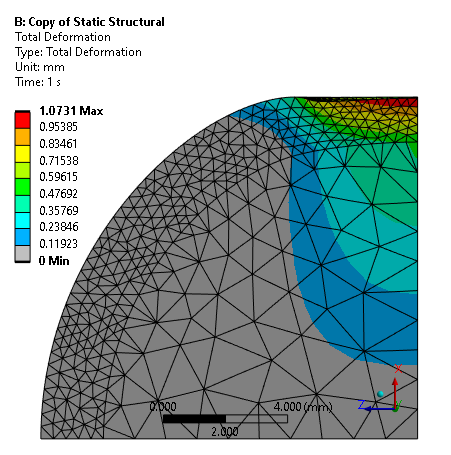
The deformation plot below is shown with a display scale factor of 1 True Scale. You can see that the top of the interior cavity has flattened out somewhat.
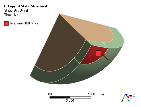
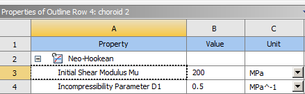
In the “B” model shown above, I created a material choroid 2 and used vastly higher Initial Shear Modulus so I could use vastly higher pressure to see some deformation and check the constant volume of the water.
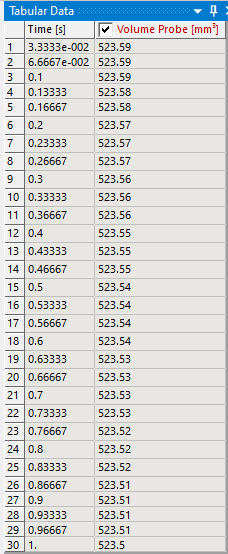
You can see that the water is holding a fairly constant volume with a Poisson’s Ratio of 0.49.
The “A” model has the original stiffness of choroid, but it can only solve up to a small pressure of 0.05 MPa.
The display scale factor shown below is 1.0 True Scale. See how the thickness of the low stiffness choriod has been squashed down.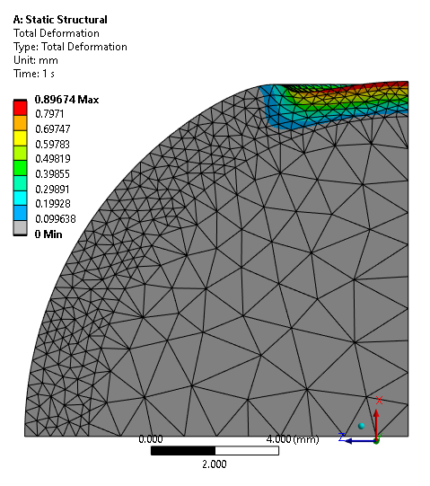
I solved this model in ANSYS 2023 R2. You won’t be able to open my model as you are using ANSYS 2020 R1 unless you upgrade to the latest version.
-
January 17, 2025 at 6:37 am
adib.aktab999
SubscriberHey I am from this new account.
Does the porus elasticity working??
I have added CPT217 on the hollow sphere which is choroid and it has to change it’s volume overtime. The volume change should be in a range of (1-2mm^3) by using this pressure.
Material property for choroid is below
Solid volume fraction: 0.55
Solid matrix:
Neo-Hookean
Elastic modulus= 0.06 MPa
Poisson’s ratio= 0
Permeability: 45037 mm2/MPa.s
Basically I am looking for the volume change overtime for the choroid to validate my model which should be like this: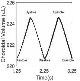
and also please share me the file. -
January 18, 2025 at 11:17 amSubscriber
-
January 18, 2025 at 7:37 pmSubscriber
Here is a link to an Ansys 2024 R2 archive of the 1/8 model of a non-porus hyperelastic solid spherical shell enclosing a volume of water represented by an orthotropic material with a pressure applied to a circular face on the shell. I built that to observe the deformation of the sphere with pressure applied on opposite sides of the sphere, but in a 1/8 model.
You could try modifying the above model by replacing the orthotropic water elements with HSFLD242 elements, though this will require some APDL code that I cannot help you with. I read that HSFLD242 elements are compatible with a quadratic tet mesh, though the figure shows it connecting to a quadratic hex element. However, after you delete the water elements (and water solid body), it is simple to mesh the choroid solid body with hex elements.
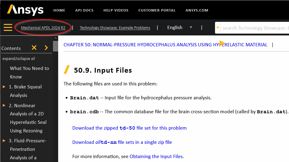
I recommend you study the Technology Showcase Example Problem Chapter 50: Normal-Pressure Hydrocephalus Analysis Using Hyperelastic Material.
This example uses porous elasticity with a neo-hookean hyperelastic material. Maybe you can apply what you learn to the 1/8 spherical shell model by adding porous elasticity and changing the elements to CPT217. -
January 19, 2025 at 4:48 pmSubscriber
I learned how to use HSFLD242 elements to represent an incompressible fluid and show how the result is very different to using the orthotropic material to represent water. Read this discussion:
I recommend you use this method for your study.
-
January 21, 2025 at 6:10 pmSubscriber
I recommend you study the Technology Showcase Example Problem Chapter 50: Normal-Pressure Hydrocephalus Analysis Using Hyperelastic Material.
This example uses porous elasticity with a neo-hookean hyperelastic material. Maybe you can apply what you learn to the 1/8 spherical shell model by adding porous elasticity and changing the elements to CPT216 or CPT217 depending on whether you mesh the choroid with quadratic hex or tet elements respectively.Note: the Input files for all the 2025 R1 Example Problems are empty zip files! You must change the version to 2024 R2 to get zip files with the promised input files.
-
January 21, 2025 at 6:14 pmSubscriber
Can you share me 2024R2 version, because it's not available rn on Ansys website.
-
January 21, 2025 at 7:00 pmSubscriber
I expect these files can be opened in older or newer versions of ANSYS.
https://ansyshelp.ansys.com/public/Views/Secured/Doc_Assets/v242/MAPDL_showcase/td-50.zip
-
January 26, 2025 at 4:53 pmSubscriber
Hey I was trying to understand the nodal loading, so I use nodal loading on a cubic model. But it doesn't show any deformation I donnow what is the reason can you give me insight?
https://drive.google.com/file/d/1P1NIQ5X8pQUIpkkZLDCFCiGwXqPwkNcH/view?usp=sharing -
January 27, 2025 at 2:02 amSubscriber
The Command object under the solid body Part1 defines the permability of the Porous Medium using a TB, PM command. A number in that command defines permeability in a certian unit system, but you have not included a comment telling me what unit system I must solve in for that number to be correctly interpreted. Always put a comment in the command to define what units to use to interpret the numbers in the command.
You have not used a Command object to change the Element Type for the mesh to use ET, 217 which is required to use TB, PM.
The solution fails with an error because Element Type 186 does not support TB, PM
If you suppress the Command under Part1, the model will solve, but zero deformation is the result because you have not used Nodal Pressure correctly. You have only selected one node on the face of the element.
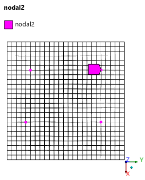
When applying a Nodal Pressure load in Ansys Mechanical, it's important to understand that the load is applied to element faces. For a nodal pressure to be created, all nodes of a given element face, including midside nodes, must be included in the node-based named selection. If you apply a nodal pressure to just one node on the face of a cube meshed with solid186 elements, it would not create an elemental face pressure unless all nodes defining that face are included [1].
URL: [1] https://ansyshelp.ansys.com/public/Views/Secured/corp/v251/en/wb_sim/ds_Nodal_Pressure.html -
February 1, 2025 at 4:03 pmSubscriberHey can you please tell me, how can I incorporate HSFLD242 element in my model. I can't find it helpful from your discussion. I have to denote vitrous body as water(HSFLD242) and choroid as CPT217. I will apply nodal pressure on choroid and vitrous body generate repulsive pressure due to incompressibility and the choroid volume will change with pressure.You have said, "However, after you delete the water elements (and water solid body), it is simple to mesh the choroid solid body with hex elements."If I delete water element, then how can I select water? But for my model it is difficult to incoparate, how can I incorporate HSFLD242??Do I have to do tetrahedral meshing for HSFLD242?? I have trier sweep meshing after compressing water solid but it isn't working and same for CPT217.
I have studied chapter 50 but that was cpt212 with neo hookian.-
February 1, 2025 at 7:51 pmSubscriber
In my January 19 reply, I provided a link to a discussion that demonstrates how to incorporate HSFLD242 elements. While that model uses Hex elements, you can get the same result with Tet elements. Either kind of element will work. Here is a link to an ANSYS 2024 R2 archive with the models shown in that discussion. https://jmp.sh/zc0UG7Le
Once you delete the water elements, the inner face of the choroid can be used to fill that interior with HSFLD242 elements, which behave like an incompressible fluid.
-
-
February 1, 2025 at 5:14 pmSubscriber
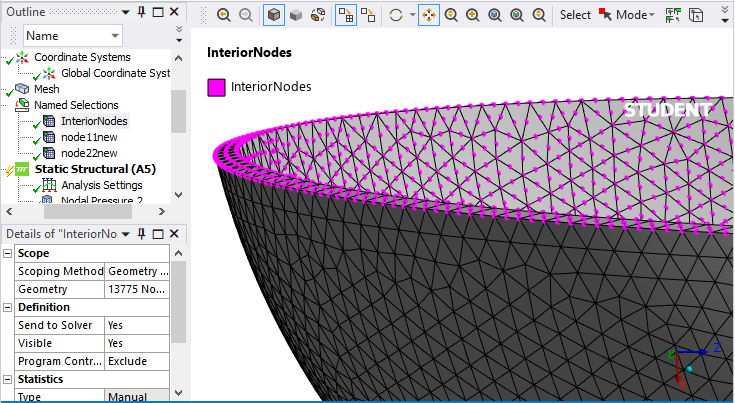
How to select internodal nodes of a whole surface??
https://drive.google.com/drive/folders/19FQFr4y9Cpfm5TyeTlqGjdfvhFeVS1jQ?usp=sharing
Many many thanks in advance for your help.-
February 1, 2025 at 9:41 pmSubscriber
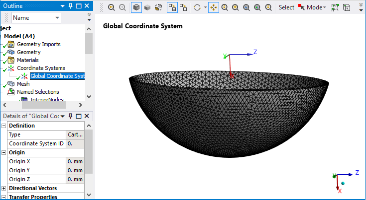
Your hollow sphere geometry is corrupt. I fixed it in this repaired version which shows how to select the InteriorNodes. Your corrupt solid had no interior face.
You can use this example model to get the HSFLD242 elements working. https://jmp.sh/9j8my5y6
-
-
February 1, 2025 at 9:18 pmSubscriber
As my choroid model will be porus hyperelastic which I intended to use CPT217, do I have to use "keyopt,matid,6,1" this code under choroid's geometry option?
-
February 1, 2025 at 9:42 pmSubscriber
You don't have to use any keyopts but this one is well know to help convergence in hyperelastic materials. Look up CPT217 in the Mechanical APDL Element Reference and see what keyopts are defined for this element.
-
-
February 1, 2025 at 10:45 pmSubscriber
Hello Peter, when I am using the element it's not convergong. Can you look into the model?
Is my nodal pressure working??https://drive.google.com/drive/folders/19FQFr4y9Cpfm5TyeTlqGjdfvhFeVS1jQ?usp=sharing-
February 2, 2025 at 2:29 amSubscriber
I looked at your model. The Fixed Support is covering the entire outer surface. That means none of those nodes can move!
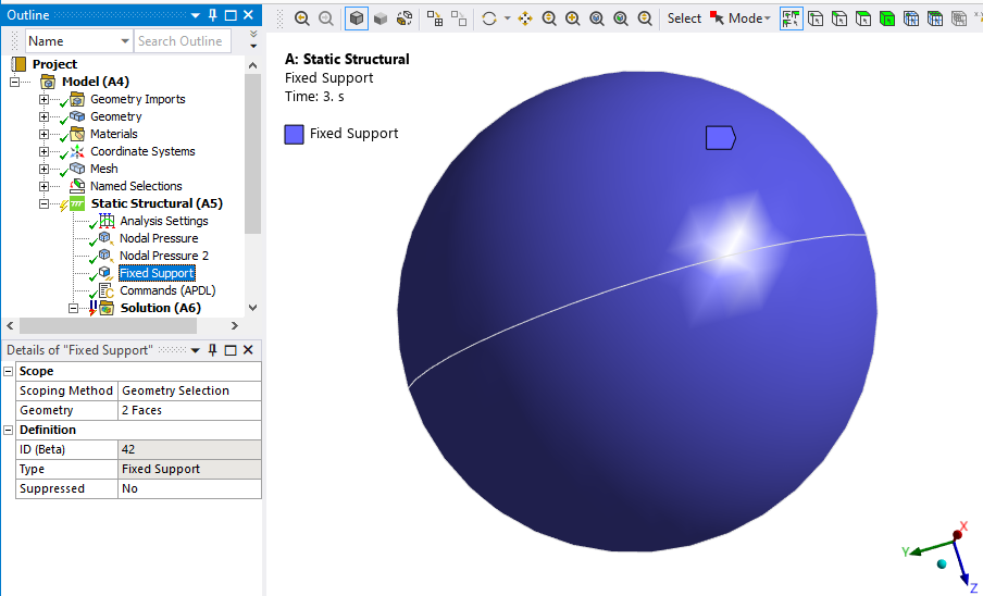
That means the effect of these nodal pressures is exactly zero!
I suggest you move the Fixed support to the thin bottom edge of the hemisphere.
I have the Student license on my personal laptop. The Student license has a limit of 128,000 nodes or elements. Your model has more than that so I would have to remesh to get below that limit. The problem is you are applying a nodal pressure so if I remesh, the Nodal Named Selections become broken. It would be better if you imprint the areas you want to apply the pressure to on the face in SpaceClaim. That way it will not be lost during remeshing.
If you want me to look at convergence issues, please keep your mesh below the 128,000 node limit. One way to cut down on the node count is to cut the model in half and use a Symmetry boundary condition on the cut face.
-
-
February 2, 2025 at 9:51 amSubscriber
From the previous file I have shared, whenever I changed the fixed support, it runs and it gives deformation not actually what I expected. Whenever I changed meshing to share with you and ran the model it is not converging. I shared the model can you look into it?
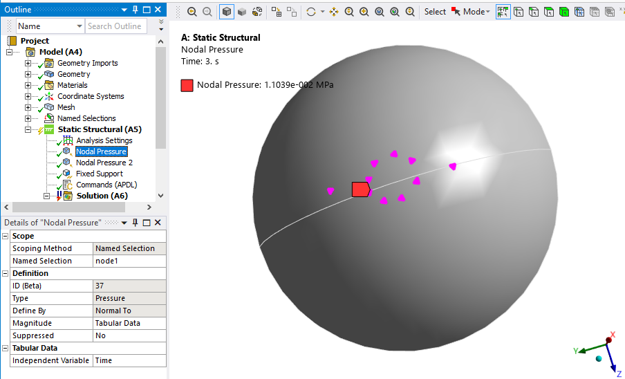
1. Is the nodal pressure applying properly??
2. Is the selecting pressure node for HSFLD242, okay or not. If not can you tell why?https://drive.google.com/drive/folders/19FQFr4y9Cpfm5TyeTlqGjdfvhFeVS1jQ?usp=sharing -
February 2, 2025 at 12:12 pmSubscriber
On the HSFLD242 elements, why did you include the narrow rim face of the hemisphere as InteriorNodes? Is there water on that face? I would exclude that face in the next model. It’s fine for now, especially since those nodes are fixed.
You put the HSFLD Node 8022 at the Global Origin. That means the water volume will have a conical top from that point down to the InteriorNodes. Is that what you want? It’s okay to leave that there for now because you will eventually have more geometry on the -X side of the origin, just be aware of the conical top if you request a report on the fluid volume.
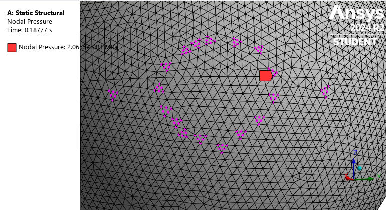
I set the Analysis to solve only step 1 and set the End Time to 0.18777 and got convergence. You can see that Nodal Pressue is causing deformation.
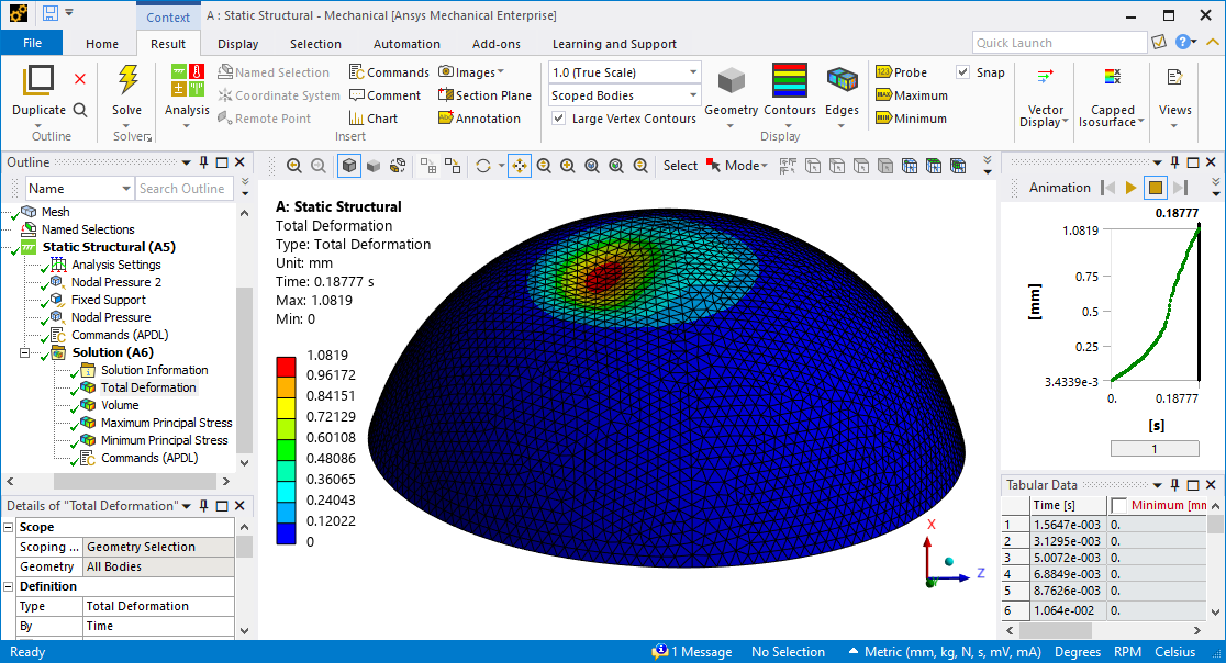
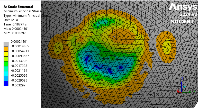
The Nodal pressure is causing compressive stress.
When you turn on Auto Time Stepping, you should make the maximum number of substeps a large number like 1000. I tried changing from the Iterative solver to the Direct solver and the time went down slightly from 9:29 to 9:11. I always use Direct unless I have a large model and the solution solves out-of-core.
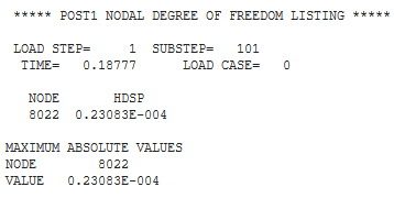
The HDFLS242 pressure node reported the pressure in the Solution Output. This number is in MPa due to the Units being set to mm.
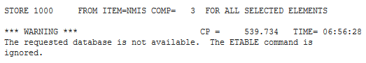
Your ETABLE command is not working.
Keep in mind that I am solving on ANSYS 2024 R2 while you are solving on 2020 R1 so your results may differ slightly from mine.
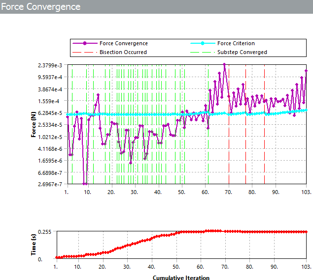
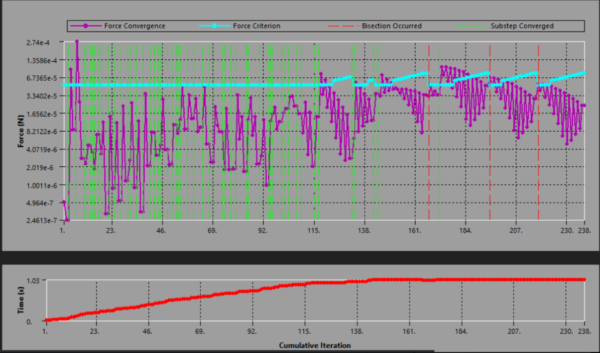
The next step is to change the end time to 1 and see if convergence continues. Looking at the Force Convergence, we see there is a problem and Interupt the solution.
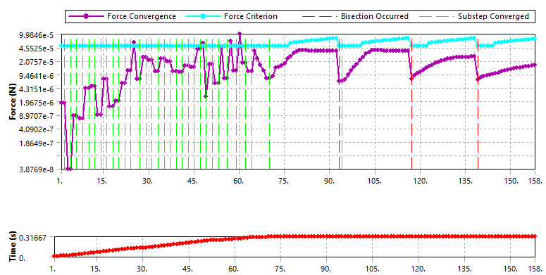
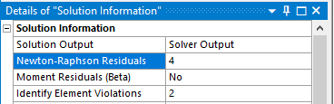
Notice that that the purple line goes horizontal, so it is unlikely to converge and after each bisection, it is not getting closer. This means it is time to look at the N-R residual plot, which you can only see if you put a number in the Newton-Raphson Residuals line of the Solution Information folder.
The reason the solver can't converge is because of a force imbalance in the elements colored red, yellow or orange below.
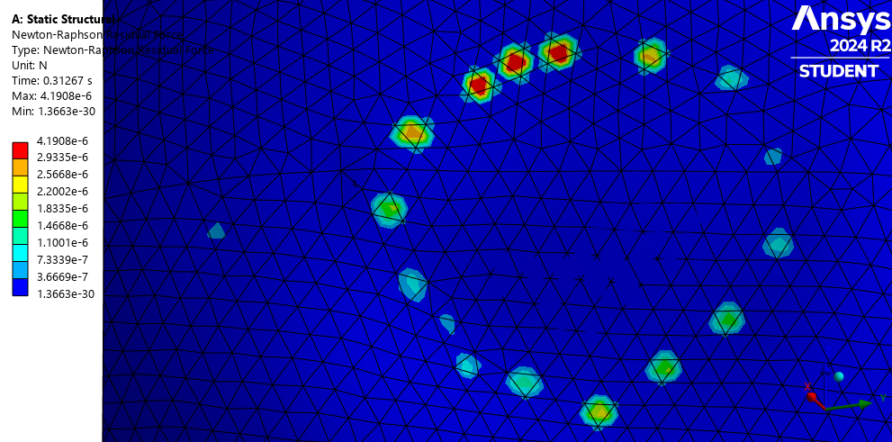
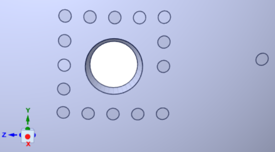
The corrective action is to apply a mesh control to use smaller elements around these regions. This is why you should stop using Nodal Named Selections for applying pressure and imprint a face on the geometry for each pressure location you want. That way, after a problem like this, you can simply apply a sizing mesh control, remesh and start solving again.
-
February 2, 2025 at 1:18 pmSubscriber
"why did you include the narrow rim face of the hemisphere as InteriorNodes?" I have done this because I couldn't select the whole interior face as nodes through box select when I am trying this some nodes remain unselected. Selecting individual nodes are frustrating.
still it's not converging.
I have added material's property newly by engineering data to solve ETABLE problem.-
February 2, 2025 at 1:47 pmSubscriber
Don't use Box select to make a Nodal Named Selection.
1. Make a new Named Selection, click on one interior face, hold the Ctrl key down and click on the other interior face.
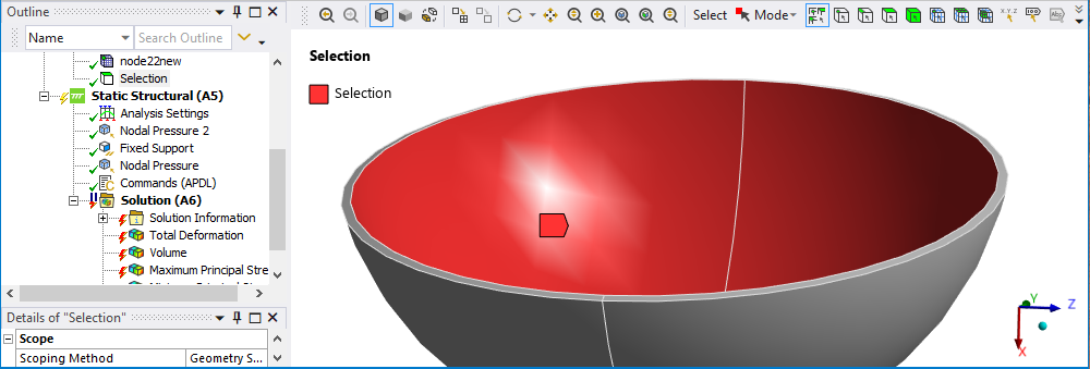
2. Right click on the Selection and choose Create Nodal Named Selection.
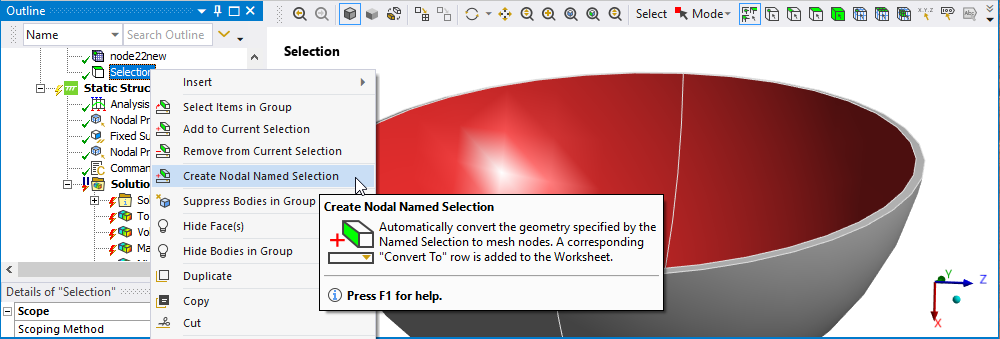
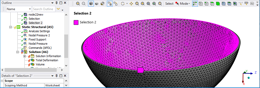
3. Rename the selections appropriately.
-
-
February 2, 2025 at 1:21 pmSubscriber
Thanks for your detailed help, I am working on it and let you know what’s happening. The last time when it's converged before decreasing mesh size, I noticed there wasn't any volume change.
-
February 2, 2025 at 1:53 pmSubscriber
The Neo-Hookean material has a small Incompressibility Parameter D1 so it is nearly incompressible. Since such a tiny area of your model has a pressure applied, the volume change might only be measured beyond the 5th digit. I created a 1/8 model with a sphere with a radius of 12 mm of that material and applied a 0.01 MPa pressure to the surface of the sphere. The surface was compressed in about 1.1 mm radially and the volume change of the1/8 solid went from 900 mm^3 to 677 mm^3.
-
-
February 2, 2025 at 1:58 pmSubscriber
May be after introducing CPT217, it will improve because the paper I want replicate the property for the choroid:
Material property for choroid is below
Solid volume fraction: 0.55
Solid matrix:
Neo-Hookean
Elastic modulus= 0.06 MPa
Poisson’s ratio= 0
Permeability: 45037 mm2/MPa.s
They got 2-3mm^3 volume change, so to validate my model I have to get the same value or close to the paper's value. -
February 2, 2025 at 2:20 pmSubscriber
I built the 1/8 spherical ball model of your Neo-Hookean material. Reread my previous reply where I put in the details.
-
February 9, 2025 at 5:52 pmSubscriber
"Your hollow sphere geometry is corrupt. I fixed it in this repaired version which shows how to select the InteriorNodes. Your corrupt solid had no interior face."
I can select interior nodes by using your node selction method in my model that I lastly shared. Isn't these are the normal nodes?
is interior nodes are different than normal nodes?
The model you have shared also not running in my 2025R1 -
February 10, 2025 at 7:22 pmSubscriber
Hello peter, I have tried with your model with imprinted face but no progress,
https://drive.google.com/file/d/13lBcVeNdG1kwlxgAYbdgsC2NRqJQ1ROf/view?usp=drive_link
this is the model I have tried recently can you please look into it??
-
February 10, 2025 at 8:10 pmSubscriber
I opened your model linked above and under the Solution Information folder, began reading the Solver Output. You must get in the habit of reading this file. At the top of the file, you can type Ctrl-F and a search bar opens, type Error and advance to the first error in the listing which is this:
*** WARNING *** CP = 4.562 TIME= 00:40:48
There are 4 HSFLD241 or HSFLD242 elements with pressure node 34840 that have negative volume. This can occur either when the element nodes
are numbered in clockwise manner or when the element face shared with the underlying solid or shell element is not facing the pressure node.
Check the element definition to make sure that the nodes are numbered in counterclockwise direction; otherwise, if the element face is not
facing the pressure node, no action is needed. The elements are saved in internal component _HSFLD348400.
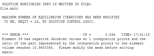
*** ERROR *** CP = 4.859 TIME= 00:40:48
Element 17148 has negative Jacobian values at 3 integration points and the ratio of the part represented by the integration points to the
element volume reaches 1.27503432. Please modify the mesh before solving again.
*** ERROR *** CP = 4.859 TIME= 00:40:48
Element 17148 (SOLID186) is turning inside out.You have to fix this error for the solver to continue.
You will also find information such as this:
*** WARNING *** CP = 2.469 TIME= 00:40:47
The sparse solver must be used if any current technology elements with u-P formulation or MPC184 elements using Lagrangian multiplier are
included in the model. The equation solver option has been switched to the sparse solver.You requested the Iterative solver, but that doesn't work on your model, you must use Direct and the program has automatically switched your solver selection.
-
February 11, 2025 at 9:33 amSubscriber
There aren't enough resource to solve this issue of my model that I provided by drive. I have applied nodal pressure 1 at +x direction(choroid's outer surface) and nodal pressure 2 at -x direction(choroid's inner surface).I have tried inreasing stiffness but nothing happened, same errors. May be imprinted face solve the issue for my model.
Btw I have tried to run your model also by changing imprinted faces' mesh size, no progress till now. -
February 12, 2025 at 4:01 pmSubscriber
When I am using your model it shows error, I am thinling using pressure on element face rather than using nodal pressure because it’s not converging at all.
When I am applying nodal pressure at your model where you imprint face that’s also gives error. The HSFLD242 file gives following error when I am using pressure at element face, the errors are below:***** MAPDL SOLVE COMMAND *****
*** WARNING *** CP = 0.609 TIME= 21:55:45
Element shape checking is currently inactive. Issue SHPP,ON or
SHPP,WARN to reactivate, if desired.
*** ERROR *** CP = 0.609 TIME= 21:55:45
Element 1234 has an undefined node number 0.
*** ERROR *** CP = 0.609 TIME= 21:55:45
Element 1235 has an undefined node number 0.
*** ERROR *** CP = 0.609 TIME= 21:55:45
The model data was checked and there were errors found.
Please check output or errors file (
F:\Thesis\_ProjectScratch\ScrDA77\file0.err ) for messages.
NUMBER OF WARNING MESSAGES ENCOUNTERED= 1
NUMBER OF ERROR MESSAGES ENCOUNTERED= 3 -
February 12, 2025 at 8:08 pmSubscriber
Use File Archive and put the HSFLD .wbpz file on your drive and link below, I will take a look.
-
February 13, 2025 at 8:22 pmSubscriber
Hello Peter, many many thanks for your continuous help.
Can you help me to provide some resource, how to imprint face on the object? I have ran the simulation with imprinted face and it is working without error.
Another question, I have to applied nodal pressure on the both surface. When I am imprinting face on both side of choroid and applied pressure on the both side. The side in which I applied HSFLD242, will make any problem?? -
February 18, 2025 at 4:43 pmSubscriber
Hello Peter, can you help me to know how can I imprint face on the object.
-
February 18, 2025 at 7:17 pmSubscriber
In SpaceClaim, create a plane using an axis. In the example below, I used the Z axis. Use the Move Tool to move the plane above the shape.

Select the Plane and start a Sketch, draw the shapes you want to imprint. I used circles.
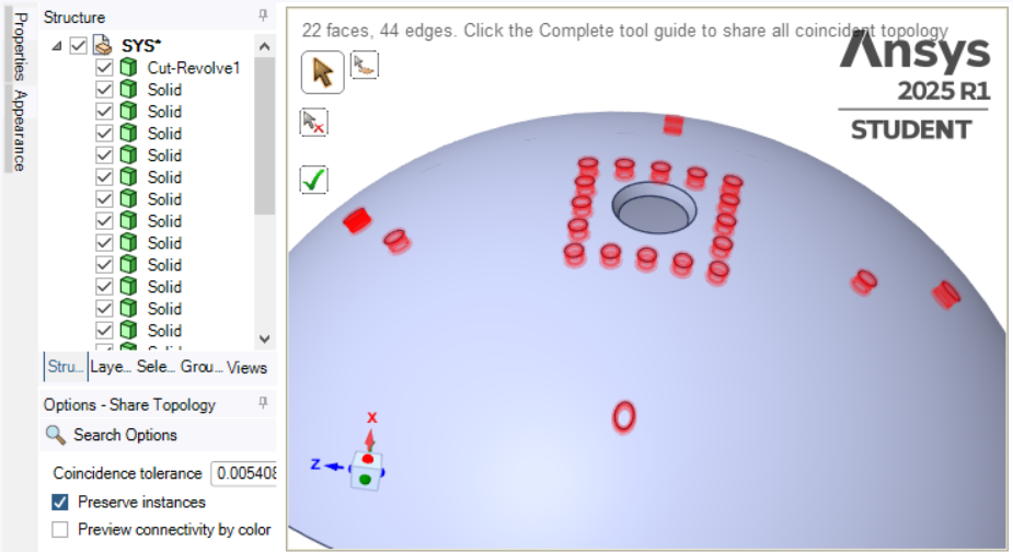
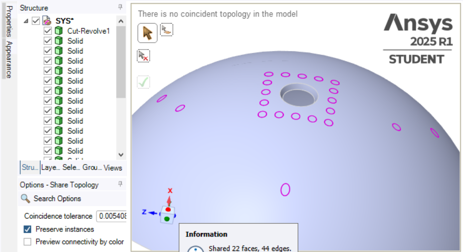
Use the Project tool to imprint the circles onto the face of the solid.
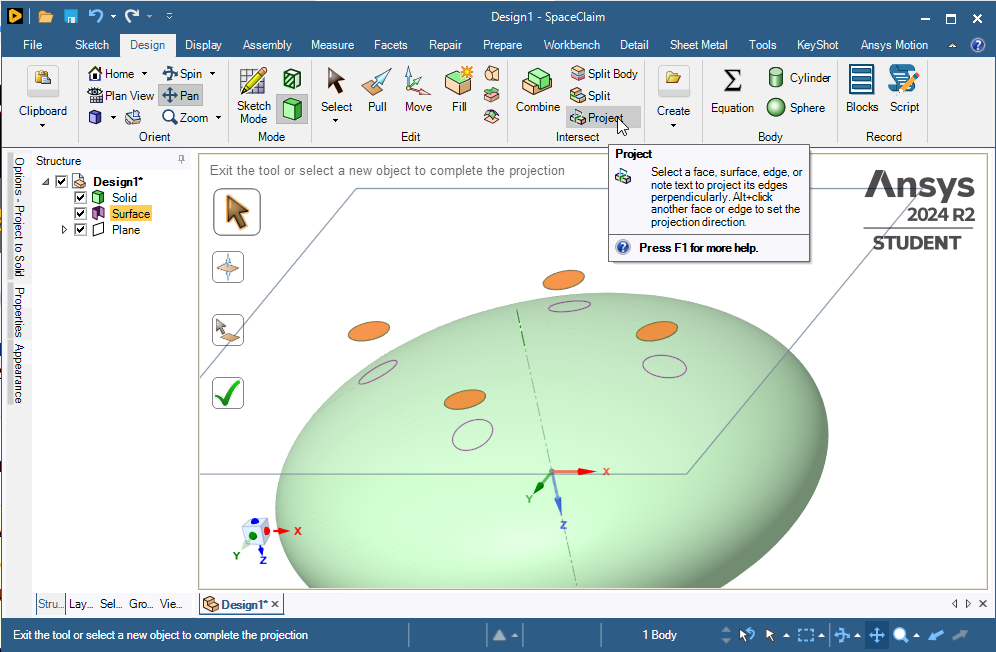
If you want a more accurate shape, make the plane tangent to the surface so there is less distortion of the shape as it projects onto a curved face.
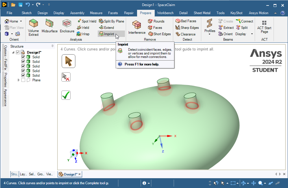
Another way is to pull the faces of the circles into solid bodies while the main solid is hidden to avoid merging into one new solid. Then on the Prepare tab use the Imprint button.
-
February 19, 2025 at 9:44 pmSubscriber
Hello Peter, can you please look into my file?? I have imprinted face and applied load but it’s not converging. On the below model, I applied normal pressure on imprinted face but this isn’t converging. Please take a look on this first, I have run it on 2020R1.
https://drive.google.com/file/d/1e-bLDJUydJJAMF80ViRdr3Jhpcklk-uM/view?usp=sharing
-
February 21, 2025 at 12:28 amSubscriber
I downloaded the 8 GB file but I have not had a chance to look at it yet because I have been travelling today and tomorrow.
-
February 22, 2025 at 9:09 pmSubscriber
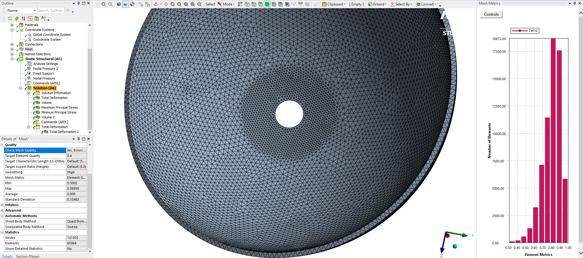
I opened the file above and see a finer mesh around the imprinted faces where you are applying load.
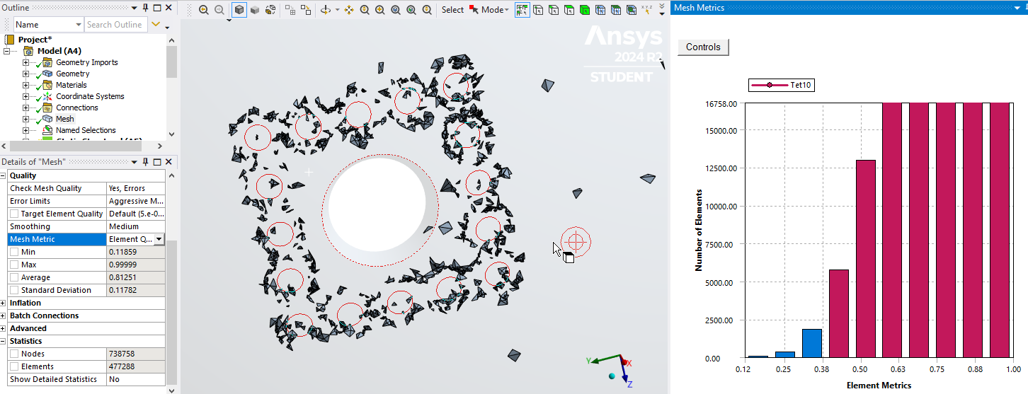
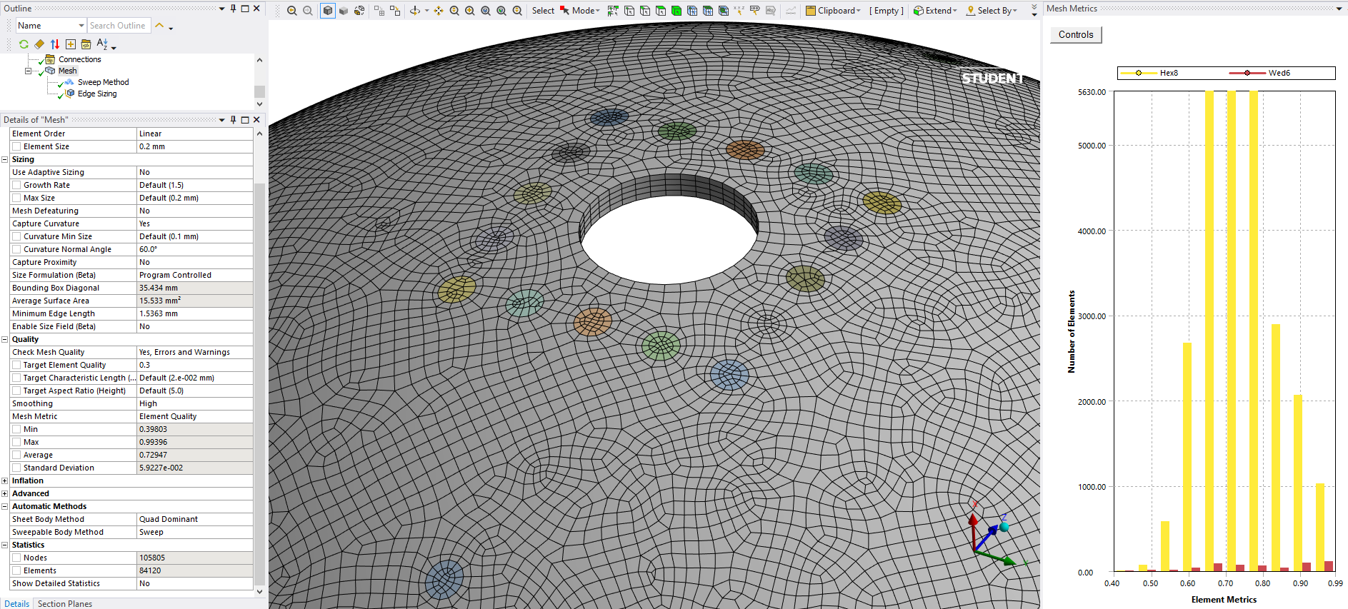
Unfortunately, the mesh quality is poor with the worst element having a 0.12 element quality.
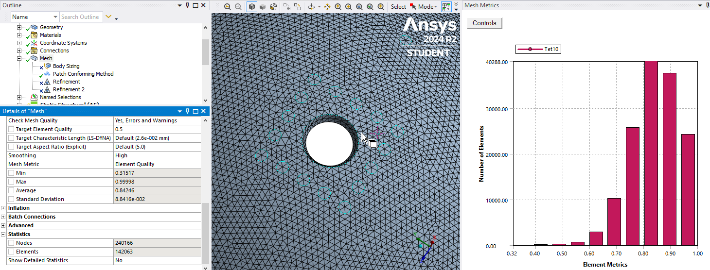
By changing the mesh parameters, I can get the mininimum element quality up to 0.32 which might help with the distorted element error and there are only 1/3 of the nodes in my better quality mesh so it will solve 3 times faster.
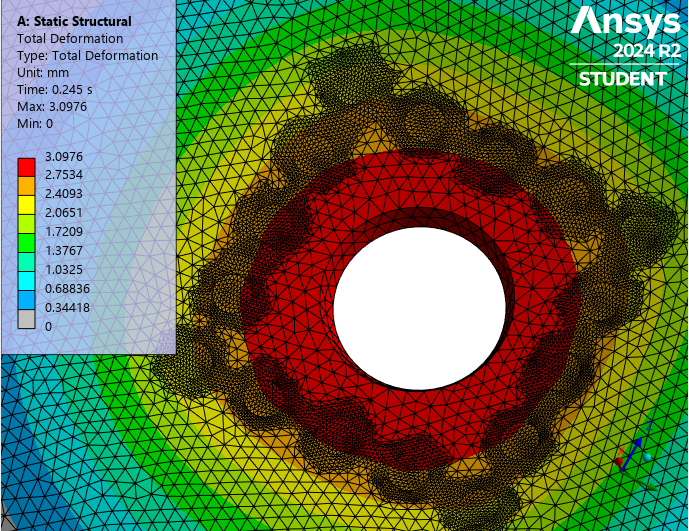
I see that the model converged up to t=0.255 s
I previously showed you how to look for the error in the Solver Output under the Solution Information folder, did you look at that?
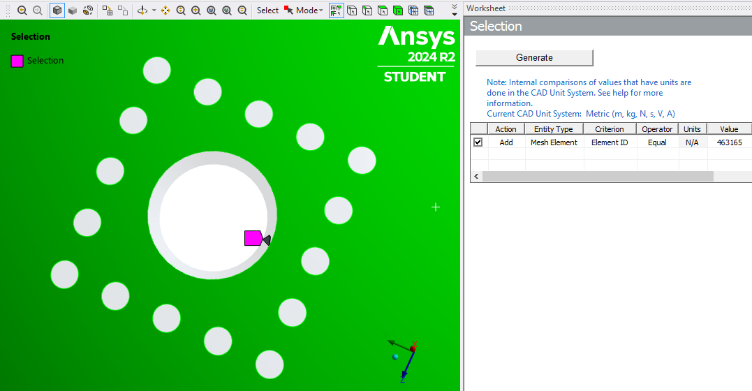
I also told you to put a non-zero number into the Newton-Raphson Residuals and Identify Element Violations. You left them at zero, which means I have to do some work to look at where the deformed element is in the mesh. However, I see you have done that in the next post below so I won't bother to look at this element in this model and will instead download a later model.
-
-
-
February 20, 2025 at 9:10 amSubscriber
Hello Peter, I have applied pressure due to long duration, I have extended from 3sec to 5sec in the imprinted face but the model isn’t converging.
I also applied extended pressure on element face. But
”warning: Mesh has elements with negative jacobian values. It might be due to the axis specified for a General Axisymmetric object under Symmetry folder is cutting through the body. Please check the results carefully.”
”Error: Element 1650 located in Body “SYS\Cut-Revolve1” (and maybe other elements) has become highly distorted. You may select the offending object and/or geometry via RMB on this warning in the Messages window. Excessive distortion of elements is usually a symptom indicating the need for corrective action elsewhere. Try incrementing the load more slowly (increase the number of substeps or decrease the time step size). You may need to improve your mesh to obtain elements with better aspect ratios. Also consider the behavior of materials, contact pairs, and/or constraint equations. If this message appears in the first iteration of first substep, be sure to perform element shape checking. Named Selections for the offending element can be created via the Identify Element Violations property on the Solution Information Object.”
these has popped out.
Below the drive link, I have tried element face pressure and extended duration. I have run this on 2025R1.
https://drive.google.com/file/d/1ZzhAkvBq5qAn09-SQJflOXERAnlJ3aXh/view?usp=sharing
How to solve this problem??
Just anyway it needs to converge by applying force on the imprinted face or element face.
I ran a simulation with imprinted face and extended time with some changes which is on the run, I will let you know what happens.-
February 22, 2025 at 10:56 pmSubscriber
This model is a non-starter. It generates an error before it even tries to converge.
A negative Jacobian is forbidden which is why you have to remesh before solving again.
You are having better results with the imprinted faces where you get convergence for a number of substeps. Keep doing that, stop doing these Nodal Selections, they are not helping.
-
-
February 20, 2025 at 1:47 pmSubscriber
I ran a simulation with imprinted face and extended time in 2020R1.
https://buetedu-my.sharepoint.com/:u:/g/personal/1918024_bme_buet_ac_bd/Eb4kU-205FdLofPQgAYgd-UBzDvW3BpPLKBe3GD3KRt5gw?e=YuGvao-
February 22, 2025 at 10:37 pmSubscriber
I would repeat the comments I made above on Feb 22 at 9:09 PM except you have a different element ID for the error. Why aren't you entering non-zero values here??? I wish I could see the N-R Residual plots, that would tell you where the solver is having problems converging. I can't solve this model as it is too large for the Student license.
This element has a high element quality > 0.75 which means that further improvements in element shape may not help. I recommend you add a Keyopt(6)=1 to the elements on the choroid body, which may help. You do that by putting the following APDL code under the SYS/Cut-Revolve1 body.
keyop,matid,6,1
Good Luck!
-
February 23, 2025 at 4:23 pmSubscriber
Look at the Total Deformation plot and you will find there is a problem with node 556976 which is listed at the bottom of the screen. This is the node you used in the Command object for the HSFLD242 elements.
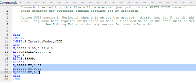
fini
/PREP7
CMSEL,S,InteriorNodes,NODE
ESLN
N,556976,0,0,0
ET,4,HSFLD242,,,,,,1
type,4
ESURF,556976,
allsel
D,556976,UX,0
D,556976,UY,0
D,556976,UZ,0
fini
/SOLU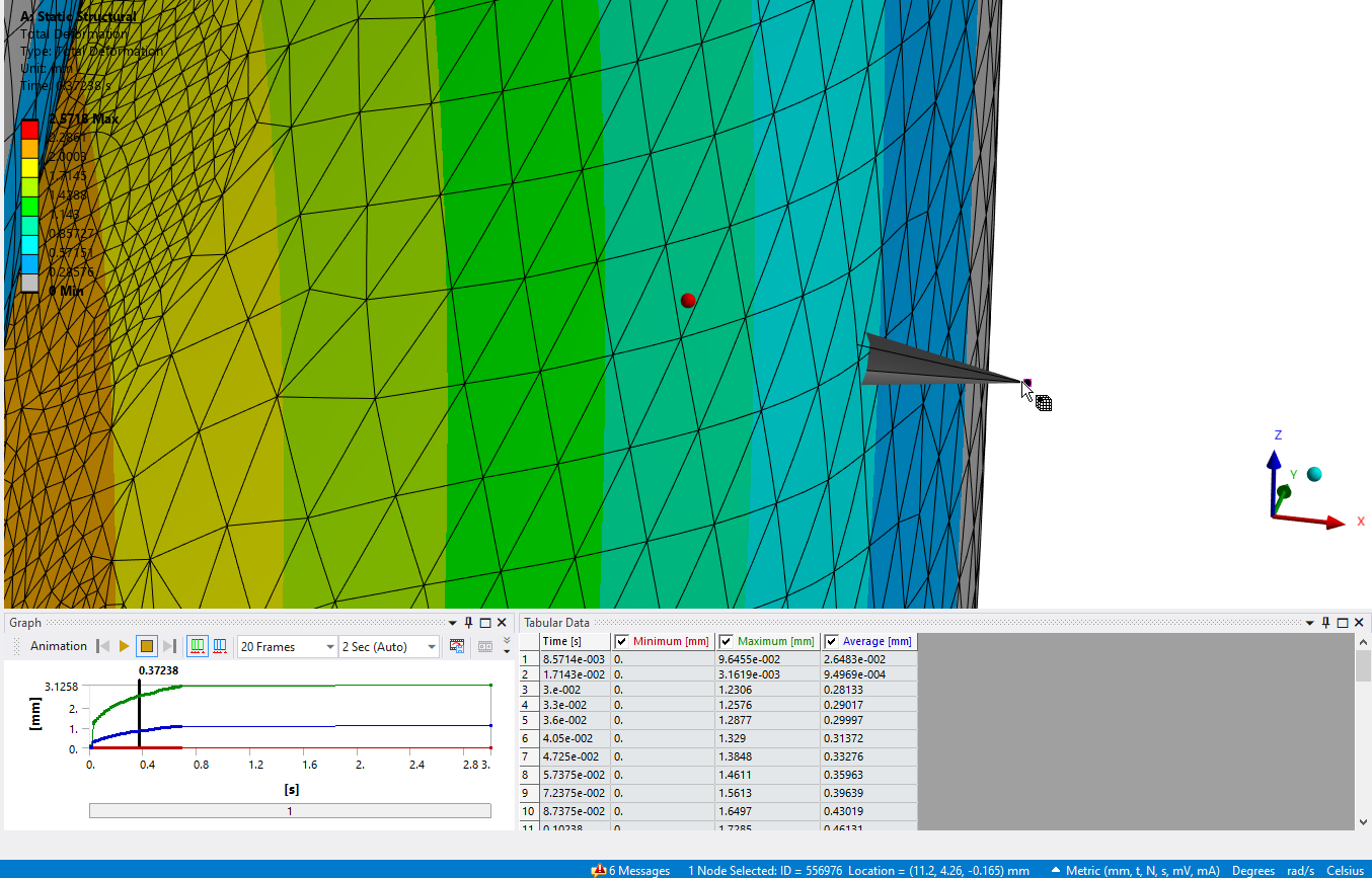
You should move that node to be at the coordinates of the center of the fixed surface (3.05,0.82,0.0) and you should use a node number outside the range of nodes in the mesh such as 9999999.
-
February 23, 2025 at 10:36 pmSubscriber
I remeshed with a coarse mesh to keep under the Student limit of 128,000 nodes and have fairly good element quality > 0.30 and the node count is only up to 98,000 so I have some room to refine the mesh.
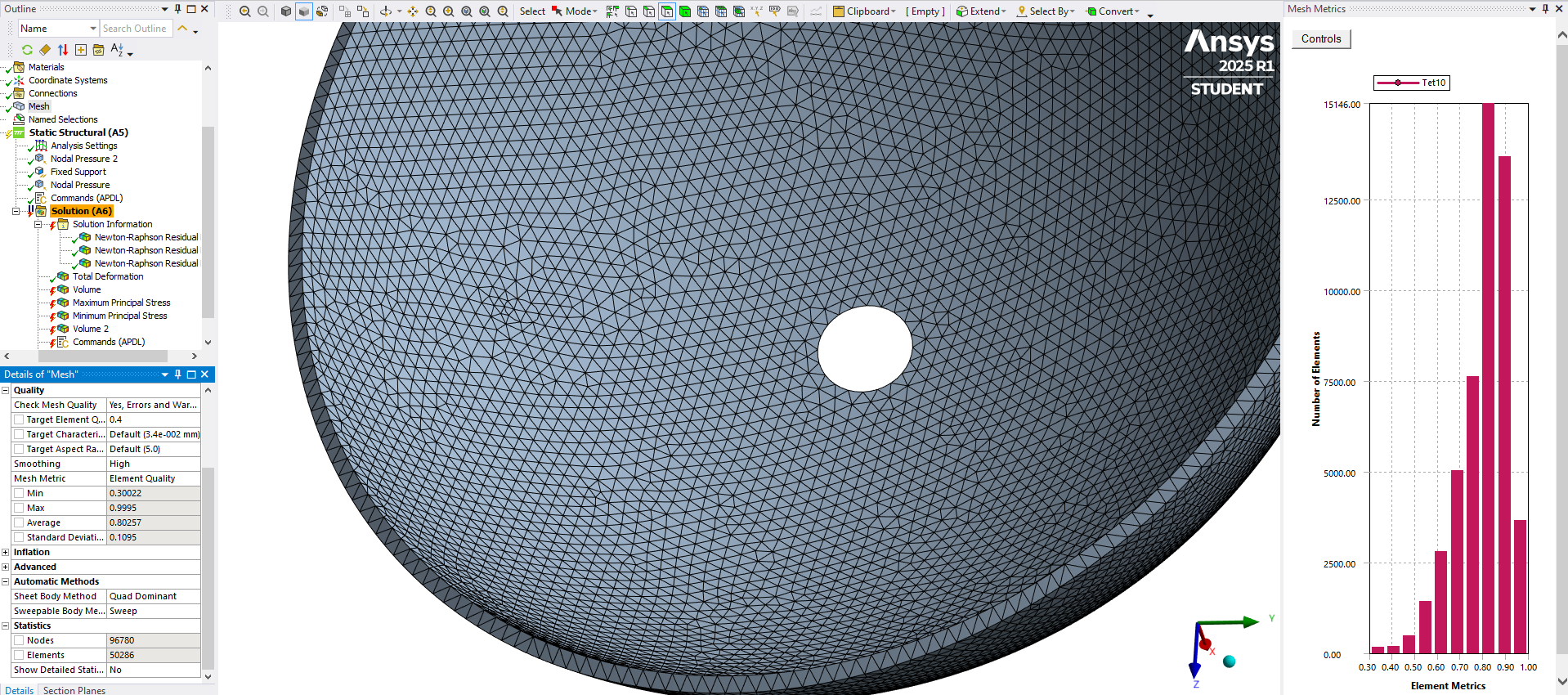
I fixed the defects you had in the coordinates and numbering of the fluid node. This time the solution did not have any highly distorted element error and it solved further than your model with the defects. I turned on the N-R Residual plot and now I see where the mesh is having difficulty converging.
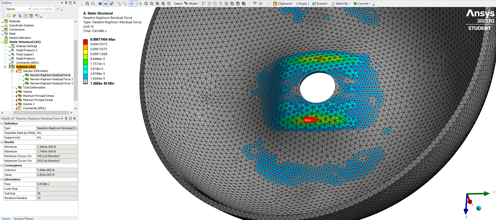
Here I put a Sizing Sphere of Influence mesh control to cut the element size in half around the problem area while keeping the node count below 128,000.
Below you can see where on the mesh the next problem area is for convergence.
-
February 24, 2025 at 9:03 pmSubscriber
Hello Peter, Thanks for your help.
I need to incorporate it in my main model soon. How can I solve this meshing problem??
I have ran the simulation with changed co-ordinate system, I will try to find the mesh errors from newton residuals. Can you suggest me a way to fix this and incorporate it in the main model? -
February 24, 2025 at 11:17 pmSubscriber
Same errors arises after changing mesh and co-ordinate number
-
-
-
February 25, 2025 at 12:20 amSubscriber
I have shown you two iterations through the process, now you must iterate multiple times through the process. You might succeed with tet elements, you might need to mesh with hex elements that sweep through the thickness. You might benefit from using Inflation layers around the pressure edges. You might benefit from using linear element order instead of quadratic element order.
Here is a 99% hex mesh with 4 linear elements through the thickness and a minimum element quality of 0.4 that might work well. I did that in Ansys 2025 R1 and here is the link to the archive.
If you have difficulty getting a simple model to converge, it is unlikely that a more complicated model will converge more easily. Building the main model will be a long and difficult task. It may take months or even years to develop all the skills needed to get an acceptable solution with the main model.
Good luck!
-
March 2, 2025 at 10:37 pmSubscriber
Hello, peter I am facing problem regarding geometry imprinting. I have successfully imprint face but when I have it made object into surface. How can I solve this issue?
https://drive.google.com/file/d/1qx108vpDPLMKMJvEm5G7dnumslXqRT3K/view?usp=drive_link
-
March 3, 2025 at 12:34 amSubscriber
Did you look at my version done in Ansys 2025 R1? Here is the link to the archive.
You have to start with the solid model. I can’t use the file you uploaded because you have lost the solid Choroid. When you get a surface for one of the imprinted faces, you have to use the Pull tool, Up To the inner surface to make a solid cylinder. Then you have to use the Combine tool to subtract that solid from the Choroid solid to make a hole through the wall thickness and have a plug to fill that hole. Then you use the Share button to have the mesh keep the bodies connected.
Here is a video to help you out. https://youtu.be/0eCHjQlNbnU
-
March 3, 2025 at 11:09 amSubscriber
I have applied nodal pressure on your model with better mesh but it also not converged and the following error has popped out:
*** ERROR *** CP = 4.828 TIME= 00:06:46
Element type 4 is not the same shape as HSFLD242. Switching to a
different shape is not allowed while elements of type 4 exist. -
March 3, 2025 at 12:55 pmSubscriber
Did the hex mesh converge to a higher pressure than the tet mesh?
-
March 3, 2025 at 12:58 pmSubscriber
No, Peter. The error has popped out at the initial. Simulation didn’t start.
But I have tried face meshing and refinement and some experimental mesh setup to improve quality on a imprinted faced model. I have applied tet mesh and I saw that model converge till 1.065s where other were terminated at 0.265s-
March 3, 2025 at 6:02 pmSubscriber
You should fix that error.
-
March 3, 2025 at 6:22 pmSubscriber
The error has popped out, when I use your hex meshed model!
Can you give me little hint on it??
-
-
-
March 3, 2025 at 11:29 pmSubscriber
I don't know how to fix that error without looking at your model in detail. Please send a link.
-
March 4, 2025 at 12:18 amSubscriber
https://drive.google.com/file/d/1DQK0xrvnSeHRIYmikhnvOP48JxWdsPN4/view?usp=drive_link
This is the model I have tried using your meshing,
https://drive.google.com/file/d/1fzlySdZvv01K897z-kXqy9xJm4g-C9P_/view?usp=drive_link
Here I implement using finer meshing on imprinted faces. -
March 4, 2025 at 12:52 amSubscriber
You have to learn some troubleshooting strategies. I opened the model with the hex mesh and got the error that you got. Then I suppressed the Command Objects that caused the error and tried to solve. I found that you forgot to add a Fixed Support. After I added that, I solved and looked at the solver output. Guess what, element type 4 has already been used, that is why you can't use it again for the fluid elements.
The next available element ID is 24. Try using that instead and you will get this after you unsuppress the Command Objects and solve.
-
March 4, 2025 at 3:11 pmSubscriber
I have applied element type 24 on your model and it shows error. It is telling to make the mesh better that is may be arising from using (0,0,0) co ordinate system. And the solution isn't converging for non linear solution.
Anyway to imprint hex on the model the space claim technique isn’t working for all the faces.
-
-
March 4, 2025 at 3:28 pmSubscriber
It would be better if you show the exact text of the error. What do you mean by using (0,0,0) coordinate system?
What do you mean the SpaceClaim technique isn't working for all the faces?
-
March 4, 2025 at 5:29 pmSubscriber
https://drive.google.com/file/d/1yo0Iv3nFE03bUuKVMgJ9SlyFwux6KJ1u/view?usp=drive_link
Here is the model, you can look into it.
-
March 4, 2025 at 5:42 pmSubscriber
Why did you go back to the old 0,0,0 coordinates for the Node for the HSFLD242 elements when I provided better values in a previous model?
-
March 4, 2025 at 5:52 pmSubscriber
If you see the Force convergence curve you can see the threshold is lower and any of the substep is converging in your model. I will try this with (3.05,0.82,0.0) and let you know what has happened. with using the co ordinate system still the convergence is far away from threshold convergence value. After changing the co ordinate system it shows:
But if you see my model which I posted on “March 4, 2025 at 12:18 am” with drive link, that simulation is converging till 1.4 sec almost and the error:
”The solver engine was unable to converge on a solution for the nonlinear problem as constrained. Please see the Troubleshooting section of the Help System for more information.” I have seen the raphson residual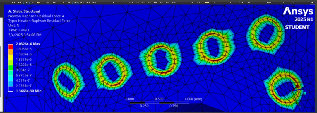
popped out and terminate.
Actually using your technique in space claim after I select pull option and select the surface and then I select the another surface then hits the enter but it isn’t creating holes. Below is the model where I have tried:https://drive.google.com/file/d/1Lfaw90Da0Xx1DCx33OM7DRjEUw_leUNQ/view?usp=drive_link
-
March 5, 2025 at 1:29 amSubscriber
Here again is the video to help you out. https://youtu.be/0eCHjQlNbnU. Study it closely.
You make solid plugs from the surfaces using Pull (No Merge), then you use the Combine tool to subtract the solid plugs from the main solid to make a hole, which includes deleting the interference solid that was created during the Combine operation. One refinement is to use the Options for the Combine tool and uncheck Keep cutter, then you don't have to delete the interference solid.
Looking at your Surface imprinting file, you are missing one surface.
-
March 5, 2025 at 10:46 pmSubscriber
Look for a mistake in the model that had such huge force values in the convergence plot.
Once you fix that mistake, it will start to look like the other one and may converge further due to the better element quality. -
March 5, 2025 at 10:48 pmSubscriber
Can you help me to understand how can you use co-ordinate value in the code?
-
March 5, 2025 at 11:00 pmSubscriber
Insert a Coordinate System and select the circular edge at the bottom of the solid.
In the Details are the coordinates of the Origin of that Coordinate System.
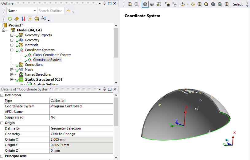
-
March 6, 2025 at 12:34 amSubscriber
Can you please look into the model, I do not understand how to converge this model. I am literally frustrated.
https://drive.google.com/file/d/1Q0ZAYA-YKbMTmjt5uxwzGQTmKq_VZgBf/view?usp=drive_link
-
-
March 6, 2025 at 1:46 amSubscriber
I downloaded that archive and first opened the Geometry cell in SpaceClaim. You forgot to use the Share button on the Workbench tab.
I showed that step in the video. That mistake would be a reason for non-convergence since all the plug bodies are unconnected.
-
March 6, 2025 at 2:19 amSubscriber
Hello Peter, lot of thanks for your continuous help. I have used the share option and try to mesh it as you have shown but still it isn't converging some weird errors popped up. Can you look into it:
https://drive.google.com/file/d/1_T4y5jC42tXOctd7KTnfbNEQ0l-DheVX/view?usp=drive_link -
March 6, 2025 at 11:39 amSubscriber
I have observed that the poor mesh has seen on the faces where the imprinted face is distorted. is this the reason of the error:
"Some of the elements on the problematic bodies can't meet the specified target metrics. Please check the elements and try changing the mesh size settings to achieve the needed mesh quality."
Do you think that for this reason my model isn't converging??
When I ran the simulation these error has popped out at the initial and solution is terminated:
"*** ERROR *** CP = 27.609 TIME= 17:28:39
An unexpected error has occurred on MPI rank 0 in the MPI software used
by Distributed ANSYS. Distributed ANSYS is unable to recover and will
terminate. Please send the data leading to this operation to your
technical support provider, as this will allow ANSYS, Inc to improve
the program."
"*** FATAL *** CP = 27.609 TIME= 17:28:39
MPI error code = 741412367 which translates to:
Unknown error class, error stack:
internal_Allreduce(1398)...................:
MPI_Allreduce(sendbuf=00000230A92CB710, recvbuf=00000230A8E55270,
count=292426, MPI_DOUBLE, MPI_SUM, MPI_COMM_WORLD) failed
MPIR_Allreduce(336)........................:
MPIDI_Allreduce_intra_composition_beta(793):
MPIDI_NM_mpi_allreduce(147)................:
MPIR_Allreduce_intra_auto(58)..............:
MPIR_Allreduce_intra_recursive_doubling(48): Unable to allocate"-
March 6, 2025 at 2:25 pm
peter.newman
SubscriberI got a similar error. You can improve the mesh quality and I think you will still get this error.
    FORCE CONVERGENCE VALUE  =  0.5361E-05  CRITERION=  0.5000E-04
    Writing NEWTON-RAPHSON residual forces to file: file.nr001
ERROR: Worker process(es) with rank(s) 3 have encountered a FATAL error.
The information below was gathered from the file*.out output file(s).
 Please review the worker process output file(s) listed below for more
 details on this error.

 Worker Process Output File .\file3.out:
 *** FATAL ***                           CP =       1.734   TIME= 22:29:28
 MPI error code = 135443726 which translates to:
 Unknown error class, error stack:
 PMPI_Waitany(287): MPI_Waitany(count=4, req_array=000000625FDF5700,
 index=000000625FDF5C98, status=000000625FDF5B00) failed
 PMPI_Waitany(270):
 (unknown)(): Unknown error class.
Notice however that the FORCE CONVERGENCE value is now a small number 0.536E-5 instead of that huge number the first time you ran this.
Under the Solve Settings, on the Home tab, if I uncheck Distributed and request 1 core, I get a different error.
*** ERROR *** CP = 0.828 TIME= 09:26:05
An unexpected error ( SIG$SEGV ) has occurred… MAPDL internal data
has been corrupted. MAPDL is unable to recover and will terminate.
Previously saved files are unaffected. Please send the data leading
to this operation to your technical support provider, as this will
allow ANSYS, Inc to improve the program.I suggest you open a new discussion to get help on this error.
-
-
-
March 6, 2025 at 9:10 amSubscriber
Hello Peter. Have you looked into my model, I just need to figure it out, soon??
-
March 6, 2025 at 2:56 pmSubscriber
Why this error is coming?? Due to interaction of complex elements??
what do you suggest to solve this error?? I haven't enough time to fix, can you suggest any other method. I need your help badly.
-
-
March 6, 2025 at 4:19 pmSubscriber
I don’t know why this error is being generated. I am not an Ansys Employee. I participate on this forum because I find some of the discussions interesting. I reply to the ones where my knowledge may be helpful and in the process, I may learn something new. That has been true of your discussion.
There is something seriously broken in this archive. When things are not going well on a complex model, retreat to a simpler model and get that working first. If you want to persue the hex meshed version of your model, go back to my model I built that used 3 planes of symmetry on a hollow sphere with a single imprinted face.
You have another model that converged past step 1 so you can make progress by building a better mesh on that. I can help with that. Is that version saved in an older version of Ansys?
-
March 7, 2025 at 10:18 amSubscriber
Hello peter, I have improved mesh and after 1.278 it terminates. can you look into the model, is there anything to do?
https://drive.google.com/file/d/15WTuDmm1-3m9baNzV71hyOKGM4r_jEg2/view?usp=drive_link
-
-
March 7, 2025 at 7:19 pmSubscriber
Hello peter, my workstation has 2023R1, the problem creating plug on the geometry. I have attached 2 files, can you look into these. If this can possible I can run the simulation on my workstation.https://drive.google.com/drive/folders/1kz6xzUFFog8qJucy0nNCk6JmW7xRwdgD?usp=sharing
-
March 7, 2025 at 7:33 pmSubscriber
I found two mistakes in the file in the 10:18 AM reply. The trival mistake is you have two Fixed Support on the same face. This doesn’t matter, it has no effect on the solution.
The other mistake is you applied a non-zero displacement to Node 99999. Why did you do that? You are supposed to hold that fixed where it is. You should look up the D command in the Mechanical APDL Command Reference.
Here is what you have:
The D command instructs the solver to move that node by those values. That is not what you want. All three values should be 0.0. I don’t know what effect that has on the solution. Maybe it causes the internal fluid to develop a pressure? You would have to do some research. In any case, I think the correct value is 0.0 for the displacement of Node 99999.
Note, that if your mesh has more than 99998 nodes, you will need to renumber this node. Change the node to 999999 and make sure that your mesh has fewer than 1 million nodes so you won’t get a collision.
-
March 8, 2025 at 9:13 amSubscriber
Can you suggest anything regarding this?
-
-
March 7, 2025 at 11:03 pmSubscriber
https://youtu.be/OZbKnxKTd_0?si=Nv-GFFto7taZfjuS
No luck in converging. SHould I apply pressure using remote point??
Or should I work on material property?
what do you suggest? Should I decrease the force amount ??
should I change element property?? -
March 8, 2025 at 2:35 pmSubscriber
Your model is converging up to the pressure when it stops converging. On the imprinted version (not shared plugs), after I changed the D commands to 0.0, it converged up to 1 second when Nodal Pressure 2 was 6.74e-4 MPa and Nodal Pressure was 3.888e-3 MPa. If you make step 1 end below those pressures, and don’t exceed those limits in steps 2, 3, 4, that is one way to go.
If you replaced pressure with Remote Points, you would have to convert pressure to force or displacement.
What physically do those pressures represent? If they represent contact with a structure, then pressure is an inaccurate representation because the stiffness of the structure making contact is not in the model. It would be more accurate to add that structure to the model.
If you changed the material model or its parameters, that could make convergence easier, but then you wouldn’t be simulating the material you should be using. Where did you get these material properties?
There are solvers that do not have any convergence requirement: Explicit Dynamics which includes LS-DYNA. The model changes from being a Static Structural model to a dynamics model. The solver works by taking extremely tiny time steps which are calculated from the time it takes a compression wave travelling at the speed of sound in the material to cross the smallest element. You would exchange all the problems of achieving static equilibrium at each substep with the problems of an Explicit Dynamics solution. The main problem is the computation could start taking tens or hundreds of hours to compute.
Changing to an explicit dynamics solver would be like starting over. You can’t use APDL commands anymore because you are no longer using the MAPDL solver. You need to mesh the fluid. You can't afford the computation time to apply the pressure over 5 seconds. If you apply the pressure over 0.5 seconds, it will only take 1/10 of the time to solve. If you apply the pressure over 0.05 seconds, it will only take 1/100 of the time to solve, but the faster you ramp up the pressure, the more inertia forces become a significant force in the simulation and the more the deformation deviates from the static equilibrium.
-
March 8, 2025 at 2:55 pmSubscriber
These pressures represent artery pressure by nodal pressure and vein pressure by nodal pressure 2. Artery pressure represents the entry of the blood and vein pressure represents exit of the blood pressure. My choroid is biphasic which author simulate in FEBio but I am trying to implement it in Ansys because of the meshing issues. Artery entry and vortex output happen through choroid's wall. Therese is sclera and retina on the surface of choroid. I can share the full model with you. I have tried to change material property and increase stiffness and compressibility parameter too. I can share the whole with you. Do you want to look into my model??
-
March 8, 2025 at 2:58 pmSubscriber
Why don't you mesh in Ansys, and export the mesh to FEBio and solve it there?
-
March 8, 2025 at 3:01 pmSubscriber
FEBio isn't that much compatible to handle a complex geometry like ours, Ansys is more compatible. I have tried FEBio but it's not working.
-
March 8, 2025 at 3:14 pmSubscriber
Yes, you mesh the complex geometry in Ansys, export the mesh to a file, then import that mesh into FEBio.
-
March 8, 2025 at 7:59 pmSubscriber
Yes I can do this. But I am implementing this using ansys.
-
-
-
March 8, 2025 at 3:08 pmSubscriber
So do those pressures cause a force to be created on the dome? If you were to model the artery as a tube that connected to the dome, the pressure on the artery walls would obviously stretch the artery and slightly increase the diameter, but the choroid is like a reservoir and the artery pressure causes the fluid to flow through the porous material from the artery to the vein. You haven't got results for the porous material in Ansys yet. Is that something you want to work on?
-
March 8, 2025 at 3:17 pmSubscriber
Are you suggesting to use porus material like CPT217 or using FSI. I haven't enough time for FSI. I have to show results on 17March. So I haven't enough time to use FSI. Do you think using porosity can help the model to converge?? What do you suggest??
Also I need to measure the volume change of choroid but after applying nodal pressure(nodal pressure for modeling cilliary artery)
-
March 8, 2025 at 3:27 pmSubscriber
I suggest you draw a Free Body Diagram of the arteries, choroid and veins. Does the choroid porous material have a non-porous membrane that keeps the blood contained? In simple terms, say a tube is anchored to ground at the free end with an internal pressure P1 at that side, and it is attached to a sphere that causes a pressure drop of dP and there is tube on the opposite side to drain the fluid with a pressure P2 where dD = P1 - P2. How does the free body diagram look for that system?
-
March 8, 2025 at 3:34 pmSubscriber
Here is what an Explicit Dynamics solution looks like. In 0.1 seconds, artery pressure ramps up to 1e-3 MPa and vein pressure ramps up to 2e-4 MPa. There is no internal fluid in this model to prevent collapse of the choroid. This solved in 12 minutes.
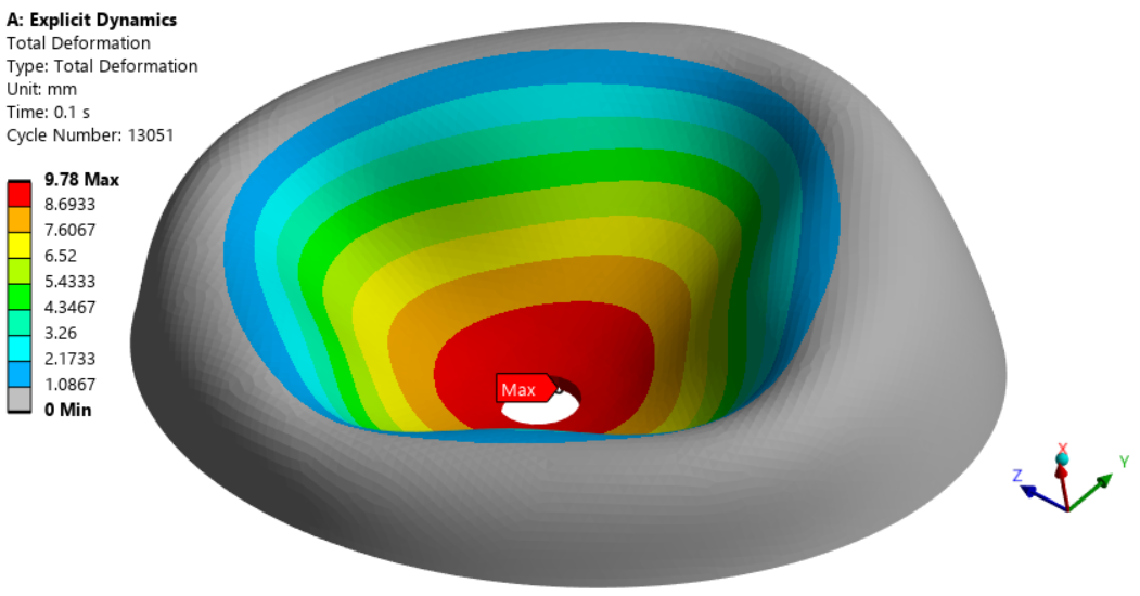
LS-DYNA probably has a good element to model the water to prevent this collapse.
-
March 8, 2025 at 3:40 pmSubscriber
Author mainly used nodal pressure to mimic the artery input and vein output. Due to the change of pressure the choroid’s volume change. Author mainly used sphere to simulate this problem. I can add artery and vein pipes to do fsi or pressure difference but if I change the geometry I haven’t enough time to do it. LS Dyna can be used to solve this issue?? If so how can I model water??
-
March 8, 2025 at 3:42 pmSubscriber
Here is the paper.
-
March 8, 2025 at 3:46 pmSubscriber
https://doi.org/10.1167/iovs.17-23454
-
March 8, 2025 at 5:17 pmSubscriber
From the paper, the authors built the mesh using one of the Ansys meshing programs: ICEM which is commonly used for CFD models and is good at creating a mostly hex mesh. I did that using Mechancial meshing with the SpaceClaim shared plugs.
The reconstructed model was then discretized into a hexahedron-dominant mesh with 67,584 eight-node hexahedra and 3024 six-node pentahedra using ICEM CFD (ANSYS, Inc., Canonsburg, PA, USA; Fig. 1). The mesh density was numerically validated through a convergence test. No symmetry conditions were applied.
-
March 8, 2025 at 5:35 pmSubscriber
From the paper, the inside of the eyeball has an IOP of 15 mmHg or a 0.002 MPa pressure. Shouldn’t that be applied to either 1) all the Interior Nodes or better still 2) the HSFLD242 node as a load in Step 1?
You can define the initial state of the hydrostatic fluid by defining initial pressure (input via the IC command with
Lab= HDSP) at the pressure node 999999
-
-
-
March 8, 2025 at 3:50 pmSubscriber
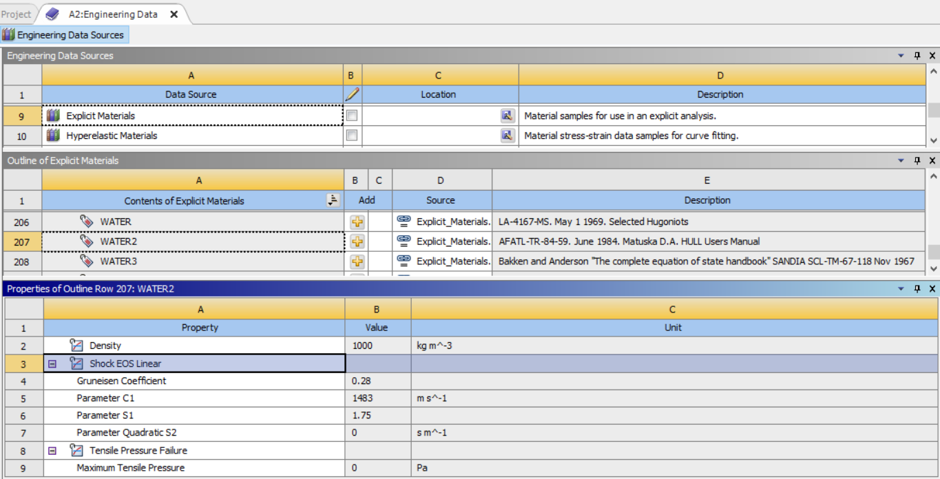
ANSYS Engineering Data Sources for Explicit Material includes three WATER models using Shock EOS (Equation of State) material models. You would mesh the inside of the sphere (using Share button first) and apply this material. You can solve either using LS-DYNA or Explicit Dyanamics.
I don’t know about using a Porous media in LS-DYNA or Explicit Dynamics. That would be something new to learn, but I just recently looked at Porus media in the Demo problem I found for you and wrote about in an old reply.
-
March 8, 2025 at 3:54 pmSubscriber
As eye has a sophisticated structure, do you think that LSDyna will give good result on this?? The demo you have sighed was for CPT212. Should I add neo hookean model from engineering data and use APDL code about CPT217 on the the geometry module and give a run on static structural. Does that help??
Is it possible to do quasi static analysis on LS dyna??
Should I change to LSDyna?? -
March 8, 2025 at 5:01 pmSubscriber
You can do a Static analysis in LS-DYNA, but it will use the implicit solver that requires convergence.
You can do a Quasi-Static analysis in the explicit solver in LS-DYNA, which is what I was describing above. It is solving the dynamics equations over a long time scale so the inertia forces remain insignificant.
I think an important step is to understand how the pressure forces act in what the authors describe as a biphasic material with a solid phase (connective tissue) and a fluid phase (blood). This is what Ansys calls a Porus Media material. Have you built a simple Ansys model to observe the expansion of the PM volume as the pressure is ramped up? Are you able to do that in a simple model in FEBio?
-
March 8, 2025 at 5:58 pmSubscriber
As far as I understood from FEBio, when choroid is assaigned as biphasic it's like choroid Think of the choroid as a **sponge** (bread) soaked in blood (milk). Pressures at arteries/veins act like **pouring/draining milk**, causing the sponge to swell/shrink.
?si=46FIZcK5ZYTy9ZoT From the video you can understood more clearly. So basically the force is applied on the fluid phase as far as I understood. Is this possible to implement by Ansys static structural?? -
March 8, 2025 at 7:10 pmSubscriber
In Mechanical APDL, the pressure in the fluid phase of porous media is typically created due to fluid flow driven by a pressure gradient. According to Darcy’s law, which defines the flow of fluids through porous media, the flow occurs when there is a difference in fluid pressure levels. This pressure difference causes the fluid to move through the porous medium, and the flow rate can be calculated based on the permeability of the medium and the viscosity of the fluid [3]. URL: [3] https://ansyshelp.ansys.com/public/account/secured?returnurl=/Views/Secured/corp/v251/en/ans_mat/elemdatatblpor.html
-
March 8, 2025 at 7:35 pmSubscriber
Scroll up in the replies to your March 8, 2025 at 3:01 pm post then scroll down and look at my replies. You will find I made some replies in-line under an older post to group my reply to your post. This makes them easy to miss compared with always replying to the bottom of this chain. Following up on the question of if IOP should be specified on the interior nodes, here is the code in the APDL snippet, notice the IC command to impose the 0.002 MPa of IOP on the Interior nodes.
fini
/PREP7
CMSEL,S,InteriorNodes,NODE
ESLN
N,999999,0.0,0.0,0.0
ET,4,HSFLD242,,,,,,1
type,4
ESURF,999999,
allsel
D,999999,UX,0.0
D,999999,UY,0.0
D,999999,UZ,0.0
IC,999999,HDSP,0.002
fini
/SOLU
Here is the result:
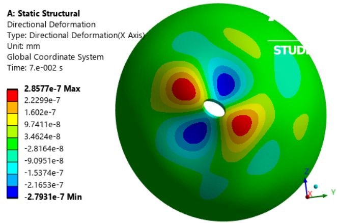
The IOP causes the dome to buckle into a mode shape, but it quickly fails to converge. It looks like the some stiffer material is needed around that hole.
-
March 8, 2025 at 7:40 pmSubscriber
The example problem you have recommened for permeability works like the biphasic material. When I have used the code for cpt212 in my model it shows:
*** ERROR *** CP = 4.453 TIME= 01:03:14Element type 285 does not support TB,PM.*** ERROR *** CP = 4.703 TIME= 01:03:14The step data was checked and there were errors found.Please check output or errors file ( C:\Users\BMELab\AppData\Local\Temp\test onchoroid.tmp1\_ProjectScratch\Scr9FBA\file0.err ) for messages.*** NOTE *** CP = 4.750 TIME= 01:03:14The Solution Control Option is only valid for single field structural,single field thermal, single field diffusion, coupledthermal-diffusion analyses and coupled-field analyses with structuraldegrees of freedom. The SOLCONTROL,ON command (if present) has beende-activated.*** NOTE *** CP = 4.750 TIME= 01:03:14The RESCONTROL command does not support fluid analyses. The RESCONTROLcommand settings have been de-activated.*** NOTE *** CP = 4.750 TIME= 01:03:14This nonlinear analysis defaults to using the full Newton-Raphsonsolution procedure. This can be modified using the NROPT command.
here is the code:et,5,212keyopt,5,3,2 ! Plane strainkeyopt,5,12,1 ! Pressure degree of freedom enabledfpx=4.8e-8tb,pm,1,,,permtbdata,1,fpx,fpx,fpxtb,pm,1,,,biottbdata,1,1.0 -
March 8, 2025 at 7:56 pmSubscriber
Peter Do I need to use the model with shared plug to do this analysis?
I have tried in my 2023 version but I don't know why the intersection isn't worked. I have done this in my laptop in 2025r1.
How can I resolve this ?
this link is added on "March 7, 2025 at 7:19 pm" comment.
I can do ICEM CFD meshing and trying to use the CPT217 on the choroid.
I am thinking of using stiffer material on the hole's around. -
March 8, 2025 at 8:09 pmSubscriber
"I suggest you draw a Free Body Diagram of the arteries, choroid and veins. Does the choroid porous material have a non-porous membrane that keeps the blood contained? In simple terms, say a tube is anchored to ground at the free end with an internal pressure P1 at that side, and it is attached to a sphere that causes a pressure drop of dP and there is tube on the opposite side to drain the fluid with a pressure P2 where dD = P1 - P2. How does the free body diagram look for that system?"
Extremely sorry to not following the answer. It will work but this causes time if you see my geometry, I have to modify multiple parts of my geometry to do this.
https://drive.google.com/file/d/1FXBLUxVTrg8Wmys81NzzB7NoZGgvsFpB/view?usp=drive_link -
March 8, 2025 at 8:21 pmSubscriber
Look at the element shapes in the Ansys Help Mechanical APDL Element Reference.
CPT217 is a quadratic tet element.
CPT216 is a quadratic hex element
CPT215 is a linear hex element that can also be used on linear tet elements.
CPT212 is for 2D problems. You are doing a 3D problem and you meshed with Solid285, which is a linear tet element.
You have to mesh with the same element shape and element order if you want to convert the element to a different type.
-
March 8, 2025 at 10:06 pmSubscriber
Here I changed the code and the error has popped out:
*** WARNING *** CP = 60.438 TIME= 04:02:50There is not enough memory for the Distributed Sparse Matrix Solver toproceed in the in-core memory mode. The Distributed Sparse MatrixSolver will now restart using the out-of-core memory mode.*** WARNING *** CP = 60.656 TIME= 04:02:50There is not enough memory for the Distributed Sparse Matrix Solver toproceed in the in-core memory mode. The Distributed Sparse MatrixSolver will now restart using the out-of-core memory mode.*** WARNING *** CP = 60.891 TIME= 04:02:51There is not enough memory for the Distributed Sparse Matrix Solver toproceed in the in-core memory mode. The Distributed Sparse MatrixSolver will now restart using the out-of-core memory mode.*** ERROR *** CP = 61.578 TIME= 04:02:51There is not enough memory for the Distributed Sparse Matrix Solver toproceed. This is likely due to the use of pivoting while factoringthe matrix. Please increase the virtual memory on your system and/orincrease the work space memory and rerun the solver. Alternatively,using the DSPOPTION command to switch to a different memory modeand/or to specify additional memory for the solver may also help. Thememory currently allocated for the Distributed Sparse Matrix Solversolver = 130 MB.
Here is the code:
et,24,217 ! Plane strain
keyopt,24,12,1 ! Pressure degree of freedom enabled
fpx=0.138
tb,pm,24,,,perm
tbdata,1,fpx,fpx,fpx
tb,pm,24,,,biot
tbdata,1,1.0
Hey man, do you think that the plugged geometry will work?? If so I will try that and can do hexa mesh by ICEMCFD.
I saw you have tried, Can you share the file??
I couldn't understand why couldn't I create plug in ansys 2023R1. -
March 9, 2025 at 12:33 amSubscriber
Would you like to have a video meeting where you can share your screen and I can see what you are doing wrong in SpaceClaim? What time zone are you in? I am in Eastern Standard Time. Do you have a zoom account? If not we can use Google Meet? I am available tomorrow.
-
March 9, 2025 at 1:16 pmSubscriber
Let me know when is the time.
-
March 9, 2025 at 1:48 pmSubscriber
When I am trying to use the combine tools it gives a error massege which says "Unable to intersect"
-
-
March 9, 2025 at 8:06 amSubscriber
I have zoom and meet both and I am also free today. Just let me know. You can do at your mornings when it will be afternoon here. just let me know.
-
March 9, 2025 at 2:09 pmSubscriber
It’s just past 10 AM in Eastern time zone. Put a meeting link in your reply and a time for me to join. Make the meeting time at least 15 minutes from when you post to allow time for delays in seeing replies. I can join anytime in the next 2 hours.
-
March 9, 2025 at 2:40 pmSubscriber
hey Peter I am free, I am giving you the link. You can join:
https://meet.google.com/ezj-fntv-hve
-
-
March 9, 2025 at 5:08 pmSubscriber
”A solver pivot warning or error has been detected in the UX degree of freedom of node 12971 located in Solid. This is usually a result of an ill conditioned matrix possibly due to unreasonable material properties, an under constrained model, or contact related issues. Check results carefully. You may select the offending object and/or geometry via RMB on this warning in the Messages window.”
Why this error popped out??
I have used displacement option too but still it is coming??
"I have unsuppress the command for fluid material and ran the simulation still error is coming:*** ERROR *** CP = 9.438 TIME= 23:09:19
There are 12 small equation solver pivot terms (e.g., at the PRES
degree of freedom of node 13514). Please check for an insufficiently
constrained model. -
March 9, 2025 at 10:36 pmSubscriber
I installed 2023 R1 on my desktop computer and made a hexmesh on the choroid body with plugs and shared topology.
Look for this file hexmesh on choroid 2023 R1.wbpz in the For Peter folder along with the solve.out file.
I hope you can get something useful out of that. I won't be available for another meeting at 7:30 PM tonight.
-
March 9, 2025 at 10:57 pmSubscriber
Hey peter I have uploaded a file named "Converged solution" where my simulation has converged. I have changed material property I was thinking that low stiffness causing the model stability. But the problem is changing the material property the volume remained unchanged throughout the simulation. That is one problem. I think FEBio has used different parameter to define Neo Hookean model. Maybe I should focus on the material property and looking into implementing porus material. If you got anything regarding this let me know.
-
March 10, 2025 at 1:06 amSubscriber
The paper says "we estimated that the elastic modulus of the choroid was 0.06 MPa (for a given thickness of 134 μm). The Poisson's ratio of the choroid was set to 0 to allow it to expand during the cardiac cycle."
You have used Neo-Hookean with an incompressiblilty constant, but it's an effort to measure the Poisson's Ratio of your material.
You might be better off using the Porous Elasticity Model that allows you to type in a near zero Poisson's Ratio. This will allow the volume of the choroid material to change with applied pressured and fluid flow into the elements.
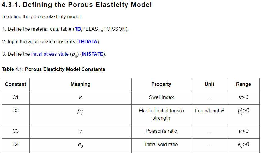
/prep7
! Porous elasticity
Kappa = 0.0024
NU0   = 0.279
pt_el = 5.835
E0    = 0.34
p0    = 69

TB,PELAS,1,,,POISSON
TBDATA,1, Kappa, pt_el, NU0, E0

/solu
!define initial stress state
INISTATE,set,dtyp,stre
INISTATE,defi,all,,,,-p0,-p0,-p0,0,0,0
Pay attention to the INISTATE command. This causes the elements to begin the simulation with some built in stress, such as the IOP which can really help convergence.
-
March 10, 2025 at 4:24 amSubscriber
But the fluid flow is though to model if. I haven't found luck in finding anything on porus material. Porus elasticity can model the deformation of the material, I think it couldn't model the fluid flow.
-
March 10, 2025 at 5:35 amSubscriber
Hey Peter I have looked that you worked on porus material before.
https://innovationspace.ansys.com/forum/forums/topic/unable-to-converge-on-a-solution/
as far as I understood CPT217 is the right model to use in my case. But now I have to understand material property properly because only for the material property the model isn't converging at all.
-
March 10, 2025 at 7:38 amSubscriber
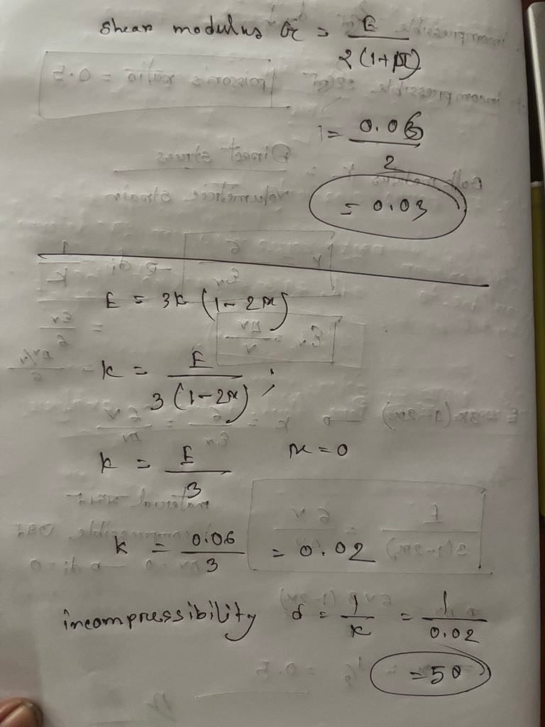 here you can see the calculation of initial shear stress and incompressibility. I have tried these with IOP but it shows element distortion error. I have uploaded the file on the drive where I named it, "hexmesh for Peter with 0.03 and 50 compressibility.
 -
March 10, 2025 at 11:43 amSubscriber
Yes, the CPT series of elements are definitely the ones you must use. That old post was a coupled structural-thermal multiphysics simulation while yours is a coupled structural-pore pressure simulation. The CPT stands for Coupled-Pore-Thermal so you can have all three physics solved simultaneously.
Good to see you digging into fundamentals with the equation. Here is what ChatGPT has to say...
The equation relating Young’s modulus E, shear modulus G, and Poisson’s ratio nu for isotropic materials:
is derived under the assumption of linear elasticity. This means it is strictly valid when strains are small and the stress-strain relationship is linear.
For nonlinear elasticity, such as in hyperelastic materials, the situation is different:
Material Nonlinearity: In hyperelasticity, the stress-strain relationship is derived from a strain energy function, which does not necessarily follow Hooke’s Law. The material properties depend on the strain level.
Generalized Moduli: The concepts of Young’s modulus, shear modulus, and Poisson’s ratio become strain-dependent in nonlinear elasticity. That is, the relationship between these moduli is no longer fixed but can change based on the deformation state.
Isotropic Hyperelasticity: While many hyperelastic materials are isotropic, their constitutive behavior is described using different forms of strain energy functions (e.g., Neo-Hookean, Mooney-Rivlin, Ogden). The linear elasticity formulas for moduli only serve as initial values for small-strain behavior but do not hold at large strains.
Thus, the equation for the relationship between E, G, and nu is not generally valid for hyperelastic materials under finite deformations. Instead, more complex expressions based on the specific strain energy function must be used to determine how these moduli evolve with deformation.
-
March 10, 2025 at 11:51 amSubscriber
I just uploaded Quarter_Symm_Choroid_In_Out_PE_2025R1.wbpz and this uses both Porus Elasticity and Porus Media.
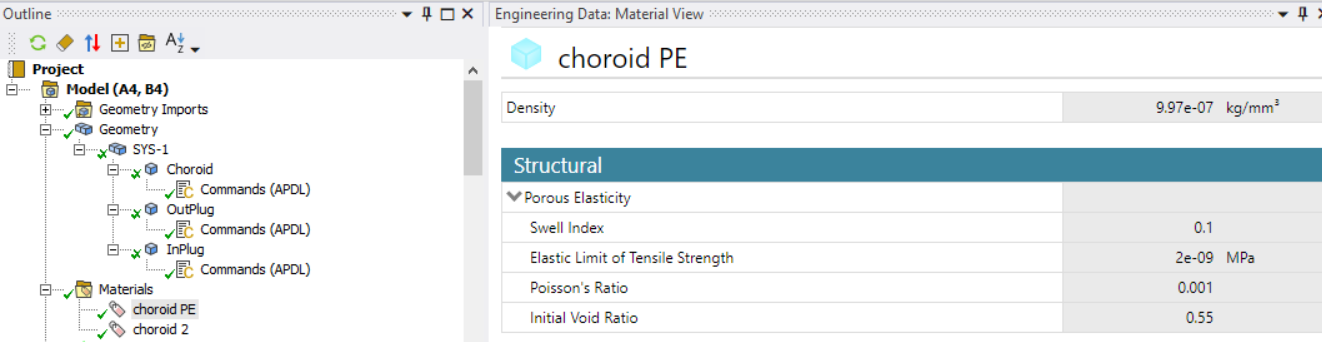
When I first ran it, I got an error that said I must have a tb,pm table so I added that in the command object under the body.
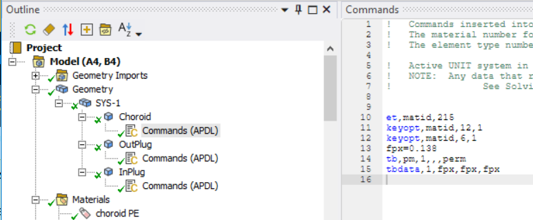
It did not converge.
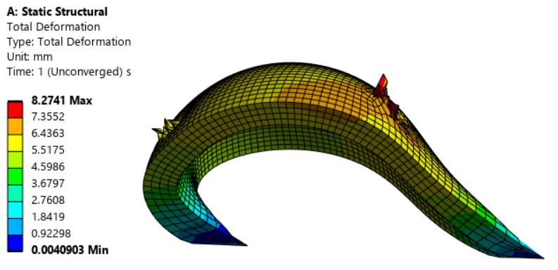
I suspect if I put an IOP pressure on the interior nodes, that would help to stabilize the structure, but when I tried to solve with just an IOP of 0.002 MPa, the model also failed to solve because the element started to turn inside out. I might try again with lower pressures.
-
March 10, 2025 at 12:34 pmSubscriber
Yes I just found out that:
The material models supported in the coupled structural-pore-fluid-diffusion analysis include elasticity (isotropic, orthotropic and anisotropic), porous elasticity, Mohr Coulomb plasticity, Cam-clay plasticity, jointed rock plasticity, extended Drucker-Prager and Drucker-Prager-based concrete plasticity.
So I couldn’t use Neo Hookean or other model to implement pore fluid diffusion.Here is another problem the permeability in the paper is 45037 mm2/MPa.s but the unit in ansys is mm/sec.
-
March 10, 2025 at 12:54 pmSubscriber
Here is the unconverged deformation of the PE model above but with a pressure of 0.002 MPa on the interior nodes. Notice how it has stabilized the shape somewhat, but has a tremendous amount of swelling of the thickness.
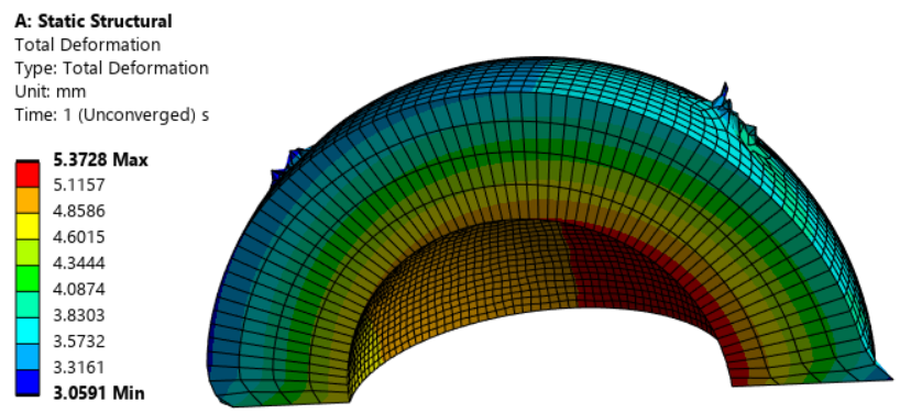
-
March 10, 2025 at 1:21 pmSubscriber
From the Ansys documentation:
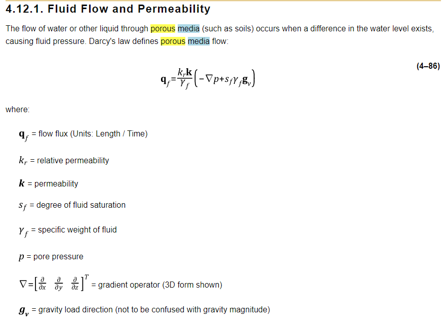
The flow flux q is in units of Length/Time. Below they call that the flow velocity.
I asked ChatGPT this:
In a pore pressure analysis, the permeability is listed as 45037 mm^2/MPa.s How could that be converted to permeability in the units of mm/s?
and it gave me
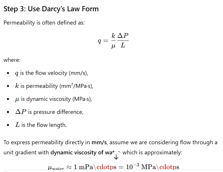
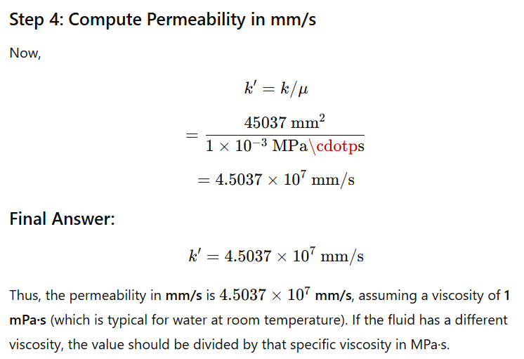
-
March 10, 2025 at 3:16 pmSubscriber
I have seen the equation and also I have tried to use gpt to do the unit exchange but I don't think that it is giving the right answer at all. For blood's permeability I thinks it is not the correct value. May be this is the reason of excessive swelling ness I couldn't understand. I have to study them and comeback at you soon.
-
-
March 10, 2025 at 3:06 pmSubscriber
Swelling is the problem here I presume. Because my model has multiple part attached to it so swelling does create a problem. I am trying to implement this on the full model with porus elasticity and CPT217.
You are doing a lot of favour to me and I am heartedly thankful to you. Can you help me to mesh the whole model with hex meshing. I have resolved geometry related problems and imprinted face on the choroid but that problem arising again in 2023R1 version of using shared cut.
I have uploaded my model in the drive. You can see the model and please help me to create hex dominant meshing on my geometry. I also trying to use ICEM CFD for meshing but it’s not working at all. Will you please look into my model??
It is named "Solved full geometry with imprinted face". -
March 10, 2025 at 4:26 pmSubscriber
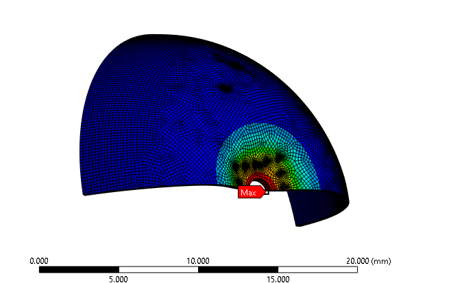
Hey Peter I have observed a problem, do you understand the issue that the water isn't interacting with the choroid. If it really interacts with the water then the pressure should be distributed but for my case the pressure is concentrated and deforms into the water which isn't the way. If you read the "Modeling of OPA" section from the paper you can understand this. That you are trying to balance through IOP, this should be balanced by the water. I think that is the reason of inconvergence. If you see my model there is a part called vitrous body(red marked in the photo) which should be the
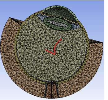
water and provide the support.
-
March 10, 2025 at 4:29 pmSubscriber
Have you figured out how swelling works? Say I have a cube of Porous Elasticity with PM enabled, meshed with CPT215. I put a pressure on the +x face of 200 Pa and a pressure on the -x face of 150 Pa, does the fluid flow through the cube along the x axis? How to plot the fluid flow result? Does the fluid leak out of the other 4 faces or are they considered non-porous? If you don’t know the answers to these simple questions, you shold build that simple model and find out. I am going to do that first since it may affect how the full eye model needs to be meshed.
It helps if you have a textbook problem with the correct answer for D'Arcy flow to see if you can build a model that gives the same answer as the textbook problem.
-
March 10, 2025 at 5:02 pmSubscriber
In my model, I add HSFLD242 elements that have a single node to monitor the pressure.
In my 1/8 model of a sphere, I show that without the HSFLD242 code, the dome collapses a lot, while with the HSFLD242 elements, the dome collapses a smaller amount and you can see the pressure in the fluid that starts at 0 pressure increase at the end of the simulation.
In my 1/8 model of a sphere, I showed that when I mesh an interior solid and use Orthotropic Elastic material with high Poisson’s ratio and low shear to simulate water, it is much stiffer than the model with the HSFLD242 elements.
In your model, you have put a mesh on the virtuous body. What material model is assigned to that?
Did you use the Share button to connect the virtuous body to the adjacent bodies?
-
March 10, 2025 at 5:10 pmSubscriber
The vitrous body is water. If I use HSFLD242, then can we change the surface of the element from the surface of choroid to the surface of vitrous body. The whole vitreous is a waterbody.
-
March 10, 2025 at 5:14 pmSubscriber
Yes I have understood but why the pressure is concentratred around the circle. This should be balanced by the water I assume.
As far as I know, swelling index is a ratio of = (Ws - Wd)/Wd
Where Ws is the weight at swelled condition and Wd is the weight of dry condition.
I am working on it.
If I use porus elastic material, this should be enough for the solid body then I don't have to use neo hookean model, right?
-
-
March 10, 2025 at 6:05 pmSubscriber
When I try to run simulation using the CPT codes of yours, I applied HSFLD material and assaign the solid material as porus elastic.
Then I am facing this error:*** ERROR *** CP = 1.641 TIME= 23:58:13
TB,PM,,,PERM has already been defined. Please delete existing table to
overwrite.
Why this error comes??
I haven't add multiple command I have checked.
Without the APDL of CPT217 it is working well. -
March 10, 2025 at 6:30 pmSubscriber
Hello Peter, if you are working on meshing, please do this in 2023R1. Because I have to run it in 2023R1.
-
March 10, 2025 at 8:14 pmSubscriber
Peter, I have done a simple change in the model where I have defined fluid through the thickness of smaller ring and it converged at 3 sec. I have defined porus elasticity due to the problem of "error" I couldn't add permeability.
Again the pressure was generating of its max through the circumference of the ring and also the volume is remaining fixed but ir should have been changed. -
March 10, 2025 at 9:22 pm
-
March 10, 2025 at 9:30 pmSubscriber
Hello Peter can you help me doing the meshing??
-
March 10, 2025 at 9:43 pmSubscriber
man do you look into my model??
-
March 10, 2025 at 9:58 pmSubscriber
Can you help me to do shared cut in the full geometry model?
-
March 10, 2025 at 11:25 pmSubscriber
I think the most important item to get working is the Porous Elasticity with Porous Media. I want to define the two phases: solid and fluid.
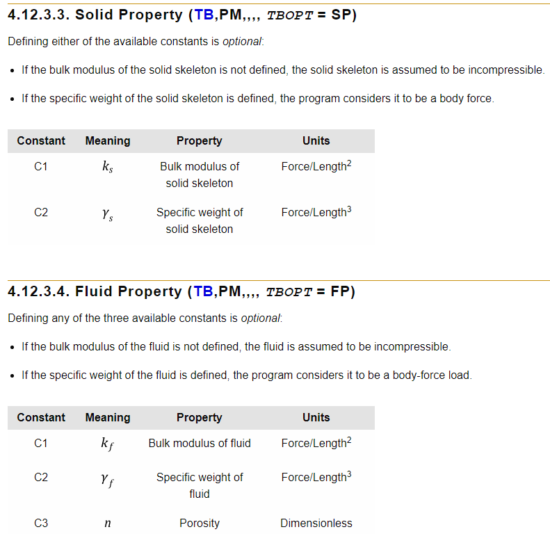
I found a good 2D example and I want to convert that to 3D with my 1/4 model.
4.7.10. Example: Initial Degree of Saturation and Relative Permeability
This example shows how to apply and use initial degree of saturation and relative permeability on coupled pore-pressure-thermal elements (CPTnnn).For more information, see Porous Media in the Material Reference./prep7
et,1,213
keyopt,1,3,2
rectng,0,0.2,0,1
esize,0.2
amesh,1
MP,EX,1,22E6 ! YOUNG'S MODULUS 22MPa
MP,NUXY,1,0.1 ! POISSON'S RATIO
FPX=1.0e-6
ONE=1.0
TB,PM,1,,,PERM
TBDATA,1,FPX
TB,PM,1,,,BIOT ! BIOT COEFFICIENT
TBDATA,1,ONE
grav_val = 9.8
KS=38e20 !---BULK MODULUS OF SAND
GS=18000 !---SPECIFIC WEIGHT OF SAND
KF=2.0e9 !---BULK MODULUS OF WATER
GF=9800 !---SPECIFIC WEIGHT OF WATER
PORO=0.46
TB,PM,1,,,SP
TBDATA,1,KS,GS
TB,PM,1,,,FP
TBDATA,1,KF,9800,PORO
TB,PM,1,,,GRAV
TBDATA,1,grav_val
TB,PM,1,,,DSAT
TBPT, DEFI,-29392.04436, 6.55E-01
TBPT, DEFI,-19496.6884 , 6.97E-01
TBPT, DEFI,-9684.84608 , 7.68E-01
TBPT, DEFI,-4019.864744, 8.55E-01
TBPT, DEFI,-2600.901772, 8.93E-01
TBPT, DEFI,-1960, 9.16E-01
TBPT, DEFI,-1303.344238, 9.47E-01
TBPT, DEFI,-379.9278504, 9.76E-01
TBPT, DEFI,0, 1
TB,PM,1,,,RPER
TBPT,DEFI,-29399.14446, 1.49E-02
TBPT,DEFI,-19506.50996, 2.86E-02
TBPT,DEFI,-9792.20116, 0.105711
TBPT,DEFI,-4375.105336, 0.28040033
TBPT,DEFI,-2800.991802, 0.50408592
TBPT,DEFI,-2143.613388, 0.7166936
TBPT,DEFI,-1955.016308, 0.7875667
TBPT,DEFI,-1675.97297, 0.84350266
TBPT,DEFI,-1583.528982, 0.8546851
TBPT,DEFI,-1303.344238, 0.92554665
TBPT,DEFI,-841.695638, 0.9739965
TBPT,DEFI,0, 1
d,all,ux,0
nsel,s,loc,y,0
d,all,uy,0
allsel
init_kr=0.92554665
init_sw=9.47E-01
inistate,set,dtyp,rper
inistate,defi,all,,,,init_kr
inistate,set,dtyp,dsat
inistate,defi,all,,,,init_sw
init_pres=-1303.344238
nsel,s,loc,y,0
d,all,pres,init_pres
allsel
nsel,s,loc,y,1
d,all,uy,0.01
allsel
finish
/solu
ANTYPE,SOIL
SSOPT,SFSW,0,-1,0,OFF,OFF ! NO FLUID WEIGHT
SSOPT,CONSOLIDATION
NROPT,UNSYM
NSUBST,50,5000,25
KBC,0 ! LOADS CHANGED IN STEPS
OUTRES,ALL,ALL
tim1 = 50
TIME,tim1
SOLVE
finish
/post1
set,first
*get, pp,node,node(0.2,0.4,0),pmsv,ppre
/out,
ppnode=pp
finish
/exit,nosaveI would eliminate the partial saturation. Once that is working, I would add the HSFLD242 elements to have incompressible water at the center of the dome. If your model can't expand in volume when the artery pressure is applied, you are missing a key piece of the simulation that was described in the paper.
-
March 10, 2025 at 11:29 pmSubscriber
What are you talking about, what was that key piece, can you let me know what am I missing?
Also, can you help me in doing the meshing of the geometry??
-
March 10, 2025 at 11:33 pmSubscriber
The model has converged by using the porus elasticity but I couldn't understand how can I incorporate CPT217, can you help me here ??
-
March 10, 2025 at 11:46 pmSubscriber
I want to see this volume of choroid expand when the pressure is applied.
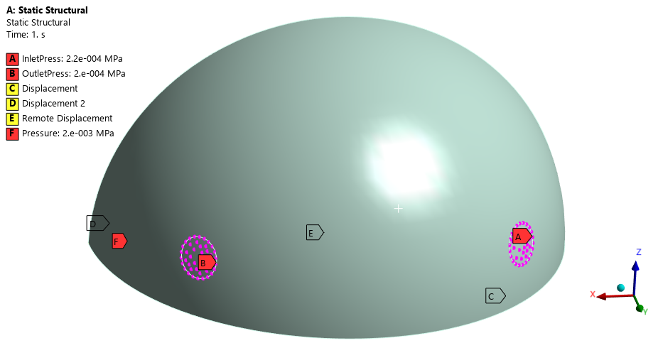
This is a single solid and the Commands change the elements to CPT215.
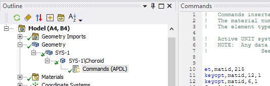
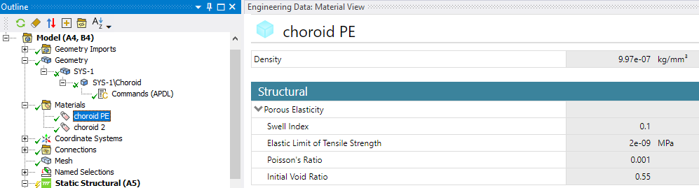
The problem with just having Porous Elasticity, is you don't get to enter the modulus of the solid phase. That is what I can do with some code in the previous reply.
-
March 10, 2025 at 11:50 pmSubscriber
Can you please elaborate, I couldn't understand. Also you are talking about the key point of the paper that I am missing. Can you please explain these??
-
March 10, 2025 at 11:59 pmSubscriber
As far I understood that porus elasticity can extract the result of solid deformation. Only tensile strength and poisson ratio can be assaigned. So I used a minimum force of the signal as tensile strength so that it can deform with the cardiac pressure change.
-
March 11, 2025 at 12:10 amSubscriber
Hey Peter can you tell me what am I missing from the paper?? It will be helpful for me...
-
March 11, 2025 at 12:19 amSubscriber
You told me and I read it in the paper that the volume of the choroid is supposed to expand. To do this you need to define an elastic modulus. You don't get that with just a Porous Elasticity material, you also need a Young's Modulus.
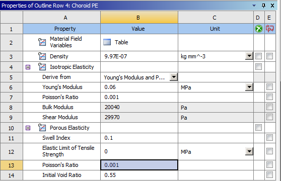
But this is not enough! You also need the PM properties to define the fluid flow so that the material can expand when the fluid is forced into it with an applied pressure. I don't know if the code below is correct or if it works, but that is what I am trying out.
FPX=0.138ONE=1.0TB,PM,1,,,PERMTBDATA,1,FPXTB,PM,1,,,BIOT ! BIOT COEFFICIENTTBDATA,1,ONEgrav_val = 9800KS=0.06 !---BULK MODULUS OF ChoroidGS=9800 !---SPECIFIC WEIGHT OF ChoroidKF=2.0e6 !---BULK MODULUS OF WATERGF=9800 !---SPECIFIC WEIGHT OF WATERPORO=0.46TB,PM,1,,,SPTBDATA,1,KS,GSTB,PM,1,,,FPTBDATA,1,KF,9800,POROTB,PM,1,,,GRAVTBDATA,1,grav_val -
March 11, 2025 at 7:13 amSubscriber
I was trying using the porus elasticity when I have used the elastic tensile strength 0.006MPa it converges till 3sec I mean the first substep. When I have make this 0.0009 it terminates at .56sec.
So I am running a simulation using porus elasticity with elastic tensile strength 0.06MPa and isotropic elasticity. But when I have used the code it shows "Element 185 doesn't require TB,PM command". And when I have used the elastic tensile strength at 0, it causes element distortion error.
Have you looked into my full geometry??
Can you help me to mesh it??
If not please help me to do the shared cut on the choroid of my full geometry. -
March 11, 2025 at 10:28 amSubscriber*** ERROR *** CP = 2.281 TIME= 16:25:34For material 26, the TB,PM,,,,PERM table can have a maximum of 9parameters. 26 have been defined.*** ERROR *** CP = 2.281 TIME= 16:25:34For material 26, the TB,PM,,,,BIOT table can have a maximum of 2parameters. 26 have been defined.*** WARNING *** CP = 2.281 TIME= 16:25:34Biot parameters defined with the TB,PM,,,,BIOT command for material 26will be ovewritten with calculations based on parameters defined withthe TB,PM,,,,SP command.*** ERROR *** CP = 2.281 TIME= 16:25:34For material 26, the TB,PM,,,,SP table can have a maximum of 2parameters. 27 have been defined
What are these error coming from?? -
March 11, 2025 at 11:32 amSubscriber
Hey Peter, can you please help me to make shared cut on the full geometry and mesh??
I have tried thousands of times doing this in 2023R1 but it’s not happening. If this shared cut is possible I can apply pressure on the nodes. Please will you see my file??
I have uploaded it in the drive. Man please let me know, it’s very very urgent else I will try something another. Just reply of this message.-
March 11, 2025 at 12:03 pmSubscriber
Hey Adib, I have uploaded the 2023 R1 archive Full_geometry_with_shared_plug_choroid.wbpz to the For Peter shared folder. This has the same shared plug geometry I shared the hex mesh of the choroid in hexmesh on choroid 2023 R1.wbpz.
-
-
March 11, 2025 at 4:15 pmSubscriber
Hey Peter, Are you free??
I need your help badly, when I am trying to implement it in a full model it gives error*** ERROR *** CP = 37.828 TIME= 22:01:18Element 541316 has an undefined node number 0.*** ERROR *** CP = 37.828 TIME= 22:01:18Element 541317 has an undefined node number 0.*** ERROR *** CP = 37.828 TIME= 22:01:18Element 541318 has an undefined node number 0.*** ERROR *** CP = 37.828 TIME= 22:01:18Element 541319 has an undefined node number 0.*** ERROR *** CP = 37.828 TIME= 22:01:18Element 541320 has an undefined node number 0.*** ERROR *** CP = 37.828 TIME= 22:01:18Element 541321 has an undefined node number 0.
When I unsupress the HSFLD command it starts running but now it is stuck.
Can you please see my model??
I need to fix it soon.
Thanks in advance.
I have uploaded my file -
March 11, 2025 at 5:47 pmSubscriber
You didn’t say what the filename was of the file you uploaded or the version of Ansys you used.
I downloaded the highlighted file and tried to open it with 2023R1 and it says it is from a future version.
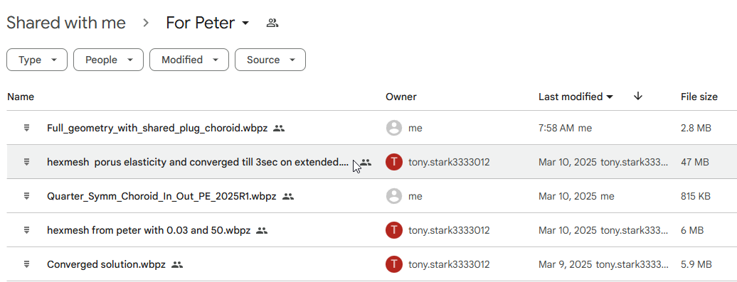
-
March 11, 2025 at 5:56 pmSubscriber
That was a big file, I think it isn't uploaded, you have seen my network connection I will upload it now.
-
March 11, 2025 at 6:05 pmSubscriber
Upload it without results, the file size will be much smaller. I can solve it after I download it.
-
March 11, 2025 at 6:18 pmSubscriber
Hey I have reuploaded the file named "Full geometry with finer mesh and command not activated"
-
March 11, 2025 at 7:36 pmSubscriber
Peter I am very confused where I should use the HSFLD element because when I have tried HSFLD without the vitreous body, there arises some contact related problems. If you can please try to fix me this.
Thanks -
March 11, 2025 at 9:36 pmSubscriber
I just uploaded hexmesh choroid with HSFLD elements and reduced pressures 2023R1.wbpz which is your file called Full geometry with finer mesh and command not activaet.wbpz that I downloaded and reduced the pressure to get the convergence to 3 seconds.
Here is a convergence plot:
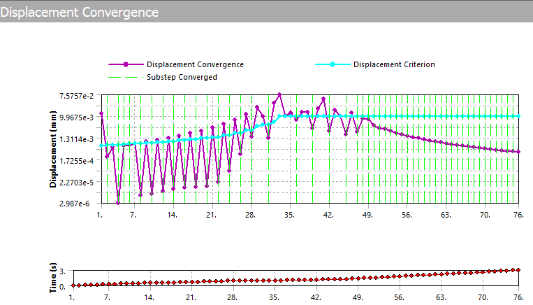
Here is the deformed shape at t=3.
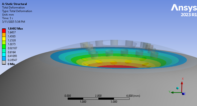
When you animate, you can see the fluid elements keep the interior fluid volume constant by applying pressure that pushes out the dome below the center when the center gets pushed in.
In the Solver Output, the fluid pressure at t=3 is 38.6 Pa while the IC for fluid pressure at t=0 was set to 2 Pa.
-
March 11, 2025 at 9:45 pmSubscriber
Can you help me to implement HSFLD element by replacing vitreous body??
-
March 11, 2025 at 10:03 pmSubscriber
- Delete (or suppress) the vitreous body (vb).
- Make a named selection called vb_faces of all the faces the vb touched, such as the interior face of the choroid.
- Convert vb_faces to a nodal named selection called vb_nodes
- Replace interiornodes with vb_nodes in the APDL code used in the model I just uploaded.
-
March 11, 2025 at 10:08 pmSubscriber
Yeah man I have tried it but it gives some contact related error, If you saw, if I delete the vitreous body then vessel doesn't get any face to contact at it's top. How can I resolve that issue. Also how can I see results that is generated by the fluid material.
-
March 11, 2025 at 11:02 pmSubscriber
Peter it is taking a lot time to converge. Do you try to do hex mesh whole geometry’s choroid. I have tried it but couldn’t. And also can you share the file of yours?? How can you converge at a very short time?? I need to work on the full geometry.
-
March 11, 2025 at 11:21 pmSubscriber
If you have got to look please let me know. Many many thanks Peter for helping me.
-
March 11, 2025 at 11:56 pmSubscriber
I can meet you in 15 minutes at 8:10 PM if you like.
-
March 12, 2025 at 12:05 am
-
March 12, 2025 at 2:31 amSubscriber
Once you finish doing split body to make all sweepable bodies and Share them, you won't have any contacts in the model so there won't be any contact errors.
-
March 12, 2025 at 8:26 amSubscriber
Can we sit on a meeting?? I am on my workstation now.
-
March 12, 2025 at 10:05 amSubscriber
Hey Peter, I am frustrated in doing meshing and all, I am not an expert either for space claim or Ansys, I just need your help badly so that I can run one simulation properly. Please help me, only 48hours remaining.
-
March 12, 2025 at 11:49 amSubscriber
Hey Peter I have tried sweep meshing on my body I have uploaded it in the drive. I couldn't do for all the faces, can you please look into it?
I really need to run one successful simulation.
my file name is "Full eye with sweep mesh tried in 2023R1" -
March 12, 2025 at 11:57 amSubscriber
I will take a look now.
-
March 12, 2025 at 12:20 pmSubscriber
Okay, I am looking at the file in Mechanical and SpaceClaim now. What is the name of the bodies you are trying to sweep mesh?
With so little time left, the best strategy is to simplify the geometry. Leave out some of tissues that are not critical to getting a result. Can you just do the back half of the eyeball?
I suggest you delete the Vessel and Piamater and add them to the model as Surface Coatings.
Simplify the geometry in this region.
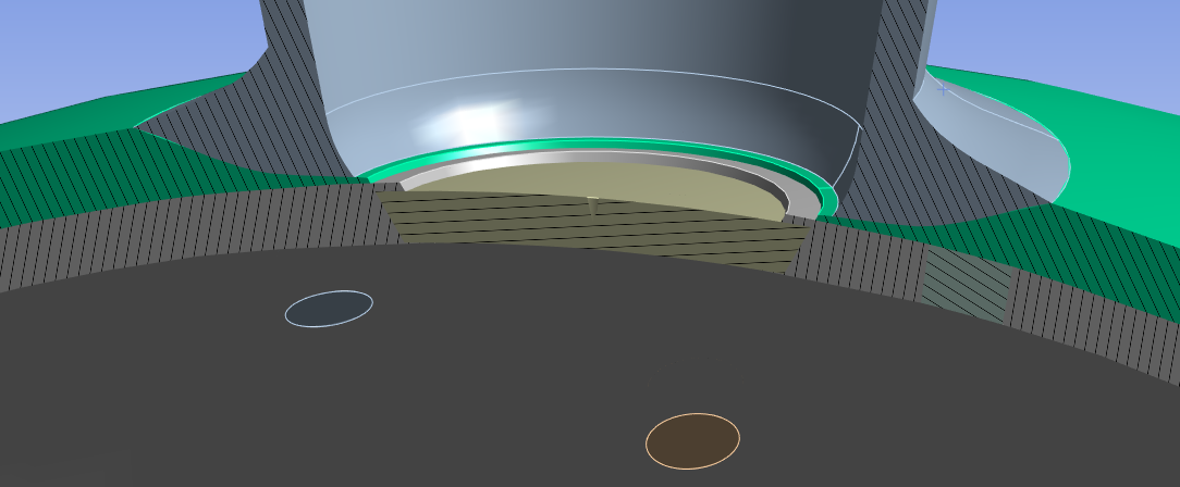
-
March 12, 2025 at 12:44 pmSubscriber
If I will simplify the geometry
I need almost all the tissues because geometry is my novelty, you can remove Nucleus from the body,
I needed the bodies because I have to exert pressure on them.
Important Geometries are:
Adipose Tissue
Choroid
Sclera
Duramater
Piamater
Revovle7
Lens
Iris
Cornea
Laminar Cribosa
Vessel
Post Laminar Neural Tissue
Retina
Okay if it is not possible to sweep all the important bodies. Can't it be possible to do sweep mesh for the bodies from where I will see results?
Other bodies can be meshed with tet elements?
what do you say? As I will work on this project later also, so the result generating bodies and pressure applying bodies can be generated by sweep and others will generate into tet mesh, what do you say?
The result generating and pressure applying bodies are:
Duramater
Piamater
Vessel
Choroid
Sclera
Laminar Cribosa
Revovle7
Adipose Tissue -
March 12, 2025 at 12:48 pmSubscriber
That's fine if you have 2 months to do it. You have 2 days. Look at the image I posted above. Sketch some straight lines in to eliminate small, thin details to make meshing easier.
-
March 12, 2025 at 12:54 pmSubscriber
”I suggest you delete the Vessel and Piamater and add them to the model as Surface Coatings.”
yeah it can be possible. If the meshing will be easier with that we can do this.
Can you just simplify and do the meshing, when you simplify the :
The result generating and pressure applying bodies are:
Duramater
Piamater
Vessel
Choroid
Sclera
Laminar Cribosa
Revovle7
Adipose Tissue
please, let me know
You can delete the nucleus from the body. -
March 12, 2025 at 1:01 pmSubscriber
If you want some bodies to sweep mesh and others to tet mesh, then you will need contact elements to hold them together. The paper did not use any contact elements which are avoided by using shared topology. It's better to have a clean hex mesh on a subset bodies and add new bodies later.
Duramater
Piamater (no body, surface coating)
Vessel (no body, surface coating)
Choroid
Sclera
Laminar CribosaRevovle7 (front half is excluded)
Adipose TissuePlease explain what tissue is in the gap between the Duramater and the Piamater?
-
March 12, 2025 at 1:15 pmSubscriber
Yeah That you said is good, if that is possible to do sweep mesh then it will be very good for me too.
The retina also added by surface right??
Post laminar neural tissues are important too.
There are no tissues in the gap between piamater and duramater.
There will be ICP fluidic pressure on that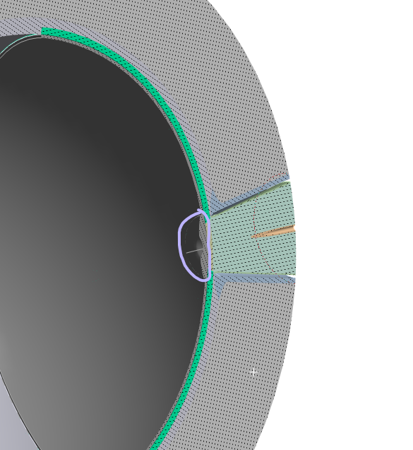
The highlighted portion is from retina, you can add that else don't need it
-
-
March 12, 2025 at 1:08 pmSubscriber
There are no tissues in the gap between piamater and duramater.
There will be ICP fluidic pressure on that -
March 12, 2025 at 1:35 pmSubscriber
To keep it simple, represent the retina using surface coating on the choroid, despite it being too thick. The circled section of retina can be a surface coating on the face of another body that fills the hole in the choriod.
Draw a simplified cross-section of this interface for sweep meshing.
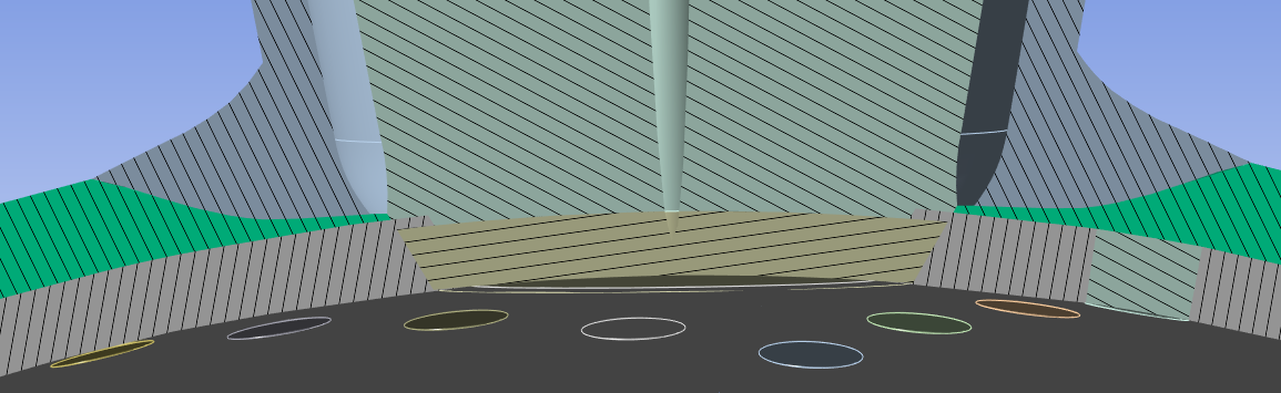
For example:
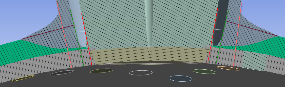
-
March 12, 2025 at 2:01 pmSubscriber
I don’t need that structure then, you can remove them. I need to make the HSFLD worked by using the geometries.
-
March 12, 2025 at 2:10 pmSubscriber
What structure do you mean by "that structure"? Make a sketch to show how the revised tissue shapes you want to keep touch each other.
-
March 12, 2025 at 2:12 pmSubscriber
This structure. I don't need it. -
March 12, 2025 at 2:40 pmSubscriber
Okay, that structure is part of the retina so that is gone.
I need you to decide how to simplify this interface. I drew some lines. How would you draw those lines?
-
March 12, 2025 at 2:58 pmSubscriber
Join my meeting when you are available. https://meet.google.com/rdu-fmqv-xvb
-
March 12, 2025 at 2:59 pmSubscriber
Can you give 10 min??
I am joining -
March 13, 2025 at 1:27 amSubscriber
Hey Peter, have you got time to work on my geometry??
-
March 13, 2025 at 1:43 amSubscriber
I haven't done anything more with it after I uploaded v1 but I will have time in the morning to spend at least an hour or two on it.
-
March 13, 2025 at 9:25 amSubscriber
It’s morning and I have time to work on your project.
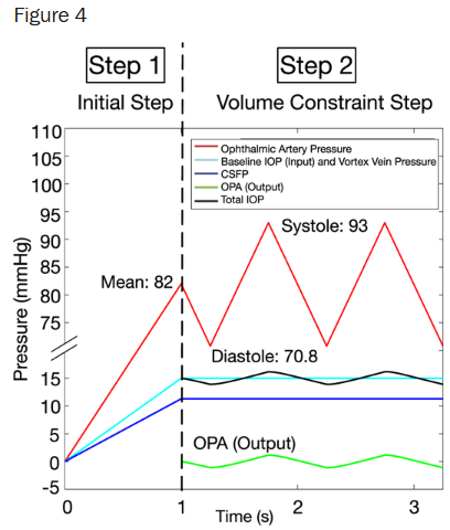
One idea to speed up the solution is to pick the two pressures for the artery and vein that you care about from this graph and have a simple 2-step solution. Step 1 has an artery pressure of 70.8 mmHg at an end time of 1 second, step 2 has an artery presure of 93 mmHg and an end time of 2 s. The reasoning is that you are performing Static Structural simulations, so time is irrelevant and none of the materials accumulate damage so the transition from one pressure to the other is conservative. The load table for pressure will just have 3 rows of time and pressure, the first row being 0,0.
-
March 13, 2025 at 11:34 amSubscriber
Yes I think it's reasonable
-
March 13, 2025 at 12:42 pmSubscriber
Hey peter can you tell me why do we change the water from orthotropic to HSFLD242??
How can I get the values of pressure that is generating into water in HSFLD??
from solver output??-
March 13, 2025 at 12:58 pmSubscriber
Read this discussion and at the end, you can see a comparison between
1) orthotropic water material meshed on a 1/4 sphere of SOLID185 elements and
2) simulating water by meshing the hollow cavity with HSFLD242 elements.
You get the water pressure in the HSFLD elements by inserting this code into the Solution branch of the model.
prnsol,hdsp
ETABLE,1000,NMISC,3
After the solve, there will be text in the solution output text file. Search for POST1 and you will find a table listing NODE 999999 and the HDSP pressure value.
-
-
March 13, 2025 at 1:56 pmSubscriber
Here is my discussion on how to get output from a Pore Pressure analysis.
-
March 13, 2025 at 2:07 pmSubscriber
Peter, have you looked into my model??
does CPT215 working on that?? -
March 13, 2025 at 2:26 pmSubscriber
Did you spend any time trying to improve the v1 geometry to get a hex mesh on it?
-
March 13, 2025 at 2:32 pmSubscriber
I have been busy preparing slides and books, I am generating results from my old model without nodal pressures.
-
March 13, 2025 at 6:25 pmSubscriber
If you have time we can meet.
-
March 13, 2025 at 7:39 pmSubscriber
I have time now.
-
March 13, 2025 at 7:54 pmSubscriber
https://meet.google.com/azd-hubv-cpy
-
March 13, 2025 at 7:55 pmSubscriber
Hey can you join?
-
March 14, 2025 at 7:40 amSubscriber
Hey peter, you have told that to expand choroid, not only porus elasticity is enough I also need young's modulus.
Why do I need that, I am using elastic tensile strength in porus elasticity isn't it enough? -
March 14, 2025 at 11:08 amSubscriber
The elastic tensile strength is used to track if the stress in the solid phase of the porous material has exceeded the yield strength and some plastic deformation is accumulating. Strength is a separate material property from modulus.
In the examples I saw, there is always a Young’s Modulus or bulk modulus defined. Could be done using APDL code such at this:
MP,EX,1,22E6 ! YOUNG’S MODULUS 22MPa
MP,NUXY,1,0.1 ! POISSON’S RATIOor you can insert Isotropic Linear Elasticicity in the Engineering data on top of Porous Elasticity and get that code written for you.
or you can insert some code for the solid phase of the Porous Media to define the bulk modulus.
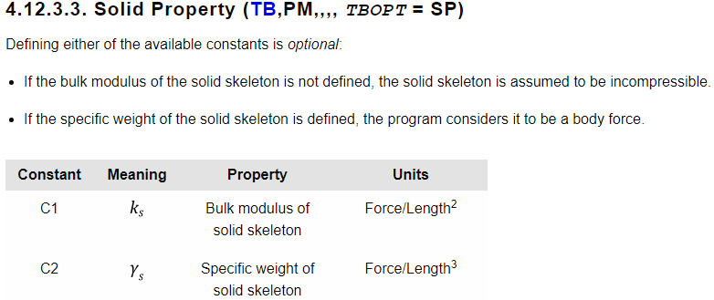
What I found odd in the model I built for my question on the forum was that I didn’t define any of those and used only Porous Elasticity. I don’t know what it used for the modulus as I didn’t provide one.
-
May 30, 2025 at 7:53 pmSubscriber
Hey peter, hope you are fine. I am thinking of start working on this and implement porous medium for my choroid. From where should I start?
-
November 15, 2025 at 6:25 pmSubscriber
Hello peter, i am facing problems to message you in reddit. Can we talk over email or thing?
If you wanna meet, let me know. I am free. -
November 15, 2025 at 6:49 pmSubscriber
You tell me you can meet in 4 hours, are you doing it??
can you please let me know, what are you planning?
-
- You must be logged in to reply to this topic.


-
peteroznewman
 5799
5799 -
scabo
 1906
1906 -
Dennis Chen
 1420
1420 -
javat33489
 1305
1305 -
Shyam Prasad V Atri
1021


© 2026 Copyright ANSYS, Inc. All rights reserved.
